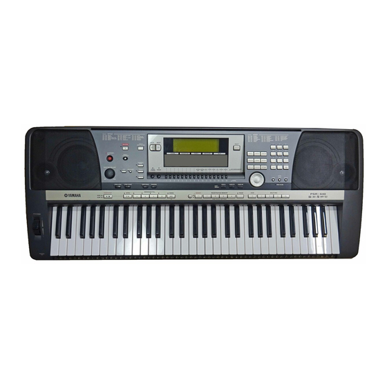
Yamaha PortaTone PSR-740 Service-Handbuch - Seite 11
Blättern Sie online oder laden Sie pdf Service-Handbuch für Musikinstrument Yamaha PortaTone PSR-740 herunter. Yamaha PortaTone PSR-740 18 Seiten.
Auch für Yamaha PortaTone PSR-740: Schritt-für-Schritt-Verfahren (21 seiten)

PSR-740/PSR-640
15
015: Output L
19
019: D/A Noise
20
020: SW,LED Chk
21
021: All LED On
22
022: Red LED On
23
023: GreenLED on
28
028: All LCD On
29
029: All LCD Off
31
031: Pedal1 Chk
33
033: PB Chk
34
034: MOD Chk
35
035: EXP Pedal Chk Connect the expression pedal (FC-7) to the [FOOT VOLUME] jack.
37
037: Midi Chk
38
038: To Host Chk
39
039: MIC Chk
(PSR-740 only)
41
041: Rom Chk2
42
042: Ram Chk2
43
043: WaveRomChk2 Checks the WAVE ROM.
46
046: BackUp Chk2
47
047: Factory Set
48
048: Test Exit
* NOTE:
The above tests Nos. 41-46, require approximately 25 minutes to conduct.
If the time is not available to perform the tests, proceed the test No.47 by pressing several the [NEXT] button.
26
Connect the level meter (with a JIS-C filter) to the [PHONES] jack. (33 ohm load)
Set the [MASTER VOLUME] at maximum and check the output level (1 kHz).
PHONES L:
-8.0 dBm +/- 2 dB
Connect the monaural plugs of the level meter (with a JIS-C filter) to the [AUX OUT] jacks.
AUX OUT L:
-6.0 dBm +/- 2 dB
Connect the level meter (with a JIS-C filter) to the [PHONES] jack. (33 ohm load)
Set the [MASTER VOLUME] at maximum. Check D/A converter noise.
PHONES L/R:
Less than -72.0 dBm (PSR-740), Less than -80.0 dBm (PSR-640)
Check the switches on the panel.
Press the switches that are displayed on the LCD. A pre-assigned note is output when
pressing the switch. (With some switches, the corresponding LED will light up.)
The test results appear on the LCD.
Check that the all LEDs on the panel are on.
Check that the all red LEDs on the panel are on.
Check that the all green LEDs on the panel are on.
Check that all LCD dots are on. The LCD becomes black.
Check that all LCD dots are off. The LCD becomes white.
Connect the foot switch (FC-4 or FC-5) to the [FOOT SWITCH] jack.
Check that the C3 note is output when pressing and releasing the pedal and the C4 note is
output when pressing the pedal again.
Check that the C3 note is output when rotating the [PITCH BEND] wheel to minimum and
the C4 note is output when rotating it to maximum.
Check that the C3 note is output when rotating the [MODULATION] wheel to minimum
and the C4 note is output when rotating it to maximum.
Check that the C3 note is output and the LCD displays 0 when pressing the expression
pedal to the lowered position and the C4 note is output and the LCD displays 127 when
backing it to the raised position.
After connecting the [MIDI IN] jack and [MIDI OUT] jack with a MIDI cable, execute the
test. Set the [HOST SELECT] switch to MIDI
Check that the C4 note is output and that the test results appear on the LCD.
For factory test use only
Connect a microphone to the [MIC/LINE IN] jack and speak to it.
Set the [MIC/LINE] select switch to MIC and set the [INPUT VOLUME] at maximum.
Check that the voice is converted to the 1-octave- upper tone without noise.
Checks the ROMs that are connected to the CPU.
The test results appear on the LCD.
Checks the RAMs that are connected to the CPU.
The test results appear on the LCD.
The test results appear on the LCD.
Performs the RAM back-up check.
Check that the display reads "NG," then turn off the power switch.
Enter the test program and perform the RAM back-up checks, then check again.
Check that the LCD displays "OK."
Note: Do not turn on the power switch by normal mode while standing by, as the
RAM data will be lost.
All the RAMs are initialized and set to the factory preset data when executing this test.
The results appear on the LCD.
Exit from the test program after executing this test.
PHONES R:
less than -50.0 dBm
AUX OUT R:
less than –50.0 dBm
