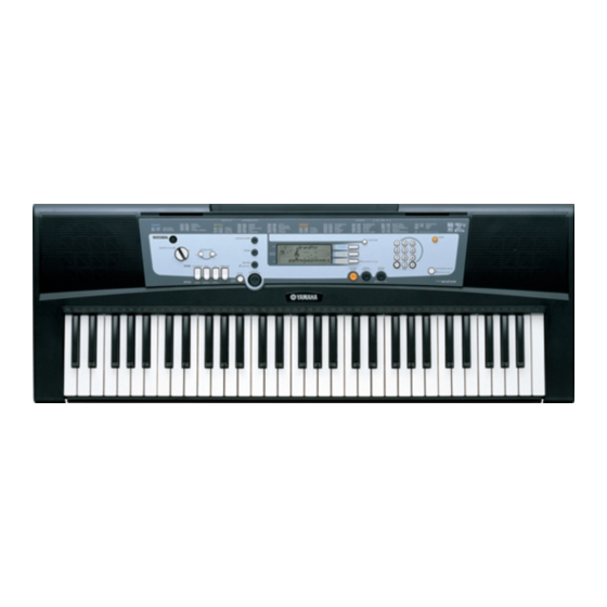
Yamaha Portatone YPT-210 Service-Handbuch - Seite 37
Blättern Sie online oder laden Sie pdf Service-Handbuch für Musikinstrument Yamaha Portatone YPT-210 herunter. Yamaha Portatone YPT-210 37 Seiten.

A
B
OVERALL CIRCUIT DIAGRAM (PSR-E213 総回路図)
PSR-E213/YPT-210
1
MK-L
(C1~B3)
MK-H
2
3
4
MK-L, MK-H: 28CC1-8819596
5
IN
MIDI I/F
MIDI
6
OUT
SUSTAIN
7
8
PNAM
2/2
PSR-E213/YPT-210
9
A
B
C
D
E
DMLCD
SYSTEM
RESET
(C4~C6)
SPEAKER R
28CC1-8834619 3
C
D
E
F
G
H
SWL01
LCD DRIVER
At reset
XX
DAC
OP AMP
POWER AMP
REGULATOR +5V
XX
F
G
H
I
J
MASK ROM 32M
MR27T3202L
PROGRAM/WAVE
XX
XX
XX
REGULATOR
+2.5V
: Ceramic Capacitor (セラミックコンデンサー)
REGULATOR
: Mylar Capacitor (マイラーコンデンサー)
+3.3V
: Semiconductive Ceramic Capacitor
(半導体セラミックコンデンサー)
: Metal Film Resistor (金属被膜抵抗)
: Not installed (未実装)
XX
Note: See parts list for details of circuit board component parts.
注: シートの部品詳細はパーツリストをご参照ください。
WARNING
Components having special characteristics are marked
specifications equel to those originally installed.
安全上の注意
印の部品は、安全を維持するために重要な部品です。
28CC1-8834620 1
交換する場合は、安全のため必ず指定の部品をご使用ください。
PNAM
1/2
XX
XX
28CC1-8834619 3
I
J
K
L
PSR-E213/YPT-210
1
2
3
4
and must be replaced with parts having
5
SPEAKER L
6
RH5RZ25CA (X3679A00)
REGULATOR +2.5V
DMLCD: IC401
PHONES /
OUTPUT
1
2
3
1: GND
2: INPUT
3: OUTPUT
BA33BC0FP (X5889A00)
REGULATOR +3.3V
DMLCD: IC402
7
2
1
3
1: INPUT
2: GND
3: OUTPUT
BATTERYS
BA50BC0T (X5887A00)
REGULATOR +5V
PNAM1/2: IC101
DC IN 12V
8
1: INPUT
AC ADAPTOR
1
2: GND
2
PA-3B/3C
3
3: OUTPUT
PSR-E213/YPT-210
9
K
L
