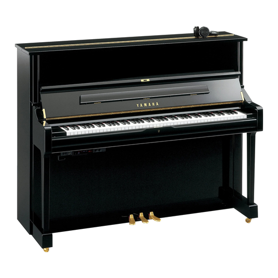
Yamaha U3-SILENT Service-Handbuch - Seite 9
Blättern Sie online oder laden Sie pdf Service-Handbuch für Musikinstrument Yamaha U3-SILENT herunter. Yamaha U3-SILENT 49 Seiten.

9.
DC IN Unit
(time required: about 1 minutes)
9-1 Remove the two (2) screws marked [81S]. The DC
IN unit S can then be removed. (Fig. B-7)
10. Pedal Unit L
(time required: about 1 minutes)
10-1 Remove the lower front board. (See Procedure A-2)
10-2 Remove the two (2) screws marked [61S]. The pedal
unit L can the be removed. (Fig. B-3, 8)
Pedal unit L
11. Pedal Unit S
(time required: about 1 minutes)
11-1 Remove the lower front board. (See Procedure A-2)
11-2 Remove the two (2) screws marked [71S]. The pedal
unit S can the be removed. (Fig. B-3, 9)
DC IN unit S
[81S]
U1
●
[81S]: Truss Head Tapping Screw-1 4.0X12 MFZN2BL (03747270)
(Fig. B-7)
[61S]
[61S]: Truss Head Tapping Screw-1 4.0X16 MFZN2Y (03747340)
(Fig. B-8)
Rear View
Top View
Top View
Pedal unit S
(Fig. B-9)
SILENT SB SERIES
DC IN UNIT S
Front View
Lower View
Pedal unit L
9
