Yamaha Electone HS-8 Service-Handbuch - Seite 13

Blättern Sie online oder laden Sie pdf Service-Handbuch für Elektronische Tastatur Yamaha Electone HS-8 herunter. Yamaha Electone HS-8 43 Seiten. Serie hs monitor da studio alimentato e subwoofer alimentato
Auch für Yamaha Electone HS-8: Benutzerhandbuch (2 seiten), Benutzerhandbuch (2 seiten), Benutzerhandbuch (20 seiten), Benutzerhandbuch (20 seiten), Benutzerhandbuch (21 seiten), Benutzerhandbuch (20 seiten), Benutzerhandbuch (20 seiten), Benutzerhandbuch (20 seiten), Benutzerhandbuch (20 seiten), Benutzerhandbuch (20 seiten), Benutzerhandbuch (20 seiten), Benutzerhandbuch (20 seiten), Benutzerhandbuch (20 seiten), (Englisch) Gebrauchsanweisung (20 seiten)
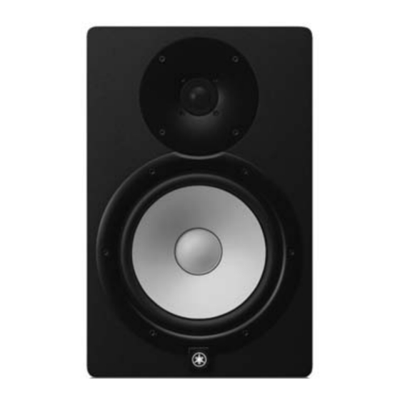
Yamaha Electone HS-8 Service-Handbuch
8.
PSW Connector Assembly, AC Circuit Board
(Time required: About 8 minutes)
8-1
Remove the PSW connector assembly soldered to the AC
circuit board and the GND connector assembly soldered
to the AC inlet. (Fig. 11)
8-2
Remove the power switch of the PSW connector assembly
by pressing its claws.(Fig. 11)
*
When installing the power switch, install so that the
white marking faces as shown in Fig. 12.
8-3
Remove the two (2) screws marked [305]. The AC circuit
board can then be removed. (Fig. 12)
8-4
Straighten the two claws of the bracket AC inlet and remove
the bracket AC inlet from the AC circuit board. (Fig. 13)
PSW connector
Soldering
assembly (Gray)
(はんだ付け)
(PSW束線 (グレー) )
AC
AC inlet
GND connector assembly
(ACインレッ ト)
(GND束線)
Fig. 11 ( 図11)
Claw
(ツメ)
AC
Fig. 13 ( 図13)
Power transformer
(電源トランス)
Soldering
(はんだ付け)
Fig. 10 ( 図10)
PSW connector
assembly (White)
(PSW束線 (白) )
Power switch
(電源スイッチ)
<HS8, HS7>
※ Destination E, B, K, O, A.
(E, B, K, O, A 仕向け)
Claw
(ツメ)
Bracket AC inlet
(ブラケットACインレット)
Soldering
(はんだ付け)
TR
8. 
PSW 束線、AC シート(所要時間 : 約 8 分)
8-1 
AC シートにハンダ付けされている PSW 束線と
AC インレットにハンダ付けされている GND 束線
を外します。 (図 11)
8-2 
PSW 束線の電源スイッチのツメを押して外します。 (図 11)
  ※ 
電源スイッチを取付けるときには、白のマーキングが図
の方向にくるように取り付けてください。 (図 12)
8-3 
[305]のネジ 2 本を外し、AC シートを外します。 (図 12)
8-4 
ブラケット AC インレットのツメ 2 箇所をまっす
ぐに伸ばして、AC シートからブラケット AC イ
ンレットを外します。 (図 13)
Rear view (背面から見た図)
Bracket AC inlet
(ブラケッ トACインレッ ト)
AC
[305] x 2
PSW connector
assembly
(PSW束線)
Fig. 12 ( 図12)
HS8/HS7/HS5
White marking
(白のマーキング)
Power switch
(電源スイッチ)
Power switch
(電源スイッチ)
[305]
AC inlet
(ACインレット)
[305]
AMP assembly
(アンプAss'y)
13