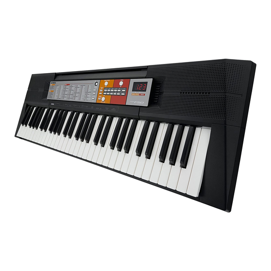
Yamaha PSR-F50 Service-Handbuch - Seite 18
Blättern Sie online oder laden Sie pdf Service-Handbuch für Elektronische Tastatur Yamaha PSR-F50 herunter. Yamaha PSR-F50 28 Seiten. Yamaha digital keyboard
Auch für Yamaha PSR-F50: Benutzerhandbuch (21 seiten), Benutzerhandbuch (21 seiten), Benutzerhandbuch (21 seiten), Benutzerhandbuch (18 seiten), Benutzerhandbuch (21 seiten), Benutzerhandbuch (4 seiten)

PSR-F50
4
Test program list
TEST
LCD display
No.
1
T01
3
T03
9
T09
11
T11
12
T12
23
T23
24
T24
45
T45
55
T55
60
T60
61
T61
•
Other Tests
Popping Noise Check
Connect the oscilloscope to the L/R of the [PHONES/OUTPUT] jack and turn on and then off the [STANDBY/ON] switch.
Make sure that popping noise level is 1.0 Vp-p or less, and that no abnormal sound or popping noise is output from the speakers.
Noise Level Check
Connect the level meter (with JIS-C filter) to the L/R of the [PHONES/OUTPUT] jack. (33 Ω load)
Set the [MASTER VOLUME] to the maximum level and check the noise level.
· PHONES L, R: –80.0 dBu or less
Battery Charging Check
Connect the AC adapter to the [DC IN] jack.
Confirm that the unit shall be performed normally, and no voltage is generated between spring terminal A - B.
18
Test descriptions, Judging Criteria
Displays version of the ROM.
"∗.∗∗"
∗.∗∗ : Version
Checks the ROM connected to the CPU bus.
Confi rm that "PAS" is displayed on the 7-segment LED.
Checks pitch accuracy.
Connect the frequency counter to the [PHONES/OUTPUT] jack. (Either L or R)
Confi rm that the correct signal is output. (441.0 Hz +/- 0.2 Hz)
Connect the level meter (with JIS-C fi lter) to the [PHONES/OUTPUT] jack. (33Ω load)
Check the output level.
OUTPUT R: -12.5 +/- 2 dBu OUTPUT L: -52.0 dBu or less
Connect the level meter (with JIS-C fi lter) to the [PHONES/OUTPUT] jack. (33Ω load)
Check the output level.
OUTPUT R: -52.0 dBu or less OUTPUT L: -12.5 +/- 2 dBu
Checks the switches on the panel.
Press the switches as shown in the 7-segment LED.
When a switch is pressed, a sound is played at the prescribed pitch.
(Refer to the switch test item list on the p.19)
Also, check that no key stick is existed.
Confi rm that "PAS" is displayed on the 7-segment LED when all the switches are pressed as
indicated.
If more than two switches are pressed at a time, "Ou2" is displayed.
To cancel the running test, press the [SONG/STYLE] button or the lowest key (white key C1)
to return to the item selection display.
Confi rm that all LEDs turned on.
Insert the plug of the AC adapter into a DC-IN 12V jack.
Confi rm that "PAS" is displayed on the 7-segment LED.
Checks the ROM connected to the CPU bus. (Full address)
Confi rm that "PAS" is displayed on the 7-segment LED.
It will take about 10 seconds for the check.
Initializes the entire backup area to reset to the factory default, and turns the power
off.
This will leave the test program, reset the system and change to the play mode.
Do not turn off the power until the main screen is displayed.
(dBu=dBm)
Auto
mode
1
2
3
4
6
5
7
8
