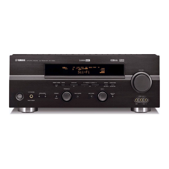
Yamaha DSP-AX450 Service-Handbuch - Seite 27
Blättern Sie online oder laden Sie pdf Service-Handbuch für Empfänger Yamaha DSP-AX450 herunter. Yamaha DSP-AX450 39 Seiten. Av receiver/av amplifier

- 1. Contents
- 2. Service Manual
- 3. Set Menu Table
- 4. Internal View
- 5. Block Diagram
- 6. Printed Circuit Board (Foil Side)
- 7. Schematic Diagram
- 8. Schematic Diagram (Operation)
- 9. Schematic Diagram (Main)
- 10. Schematic Diagram (Power)
- 11. Schematic Diagram (Subtrans)
- 12. Schematic Diagram (Video)
- 13. Exploded View
A
B
C
RX-V550/HTR-5750/RX-V450/HTR-5740/DSP-AX450
SCHEMATIC DIAGRAM (FUNCTION 1/2)
RX-V550
1
2
3
x: NOT USED
O:USED / APPLICABLE
4
5
6
7
8
0.1
0.1
0.8
0.8
0
0
MUTE
9
10
# All voltages are measured with a 10MΩ/V DC electronic volt meter.
# Components having special characteristics are marked s and must be replaced
with parts having specifications equal to those originally installed.
# Schematic diagram is subject to change without notice.
76
D
E
F
0
0
0
0
0
0
0
0
0
0
0
0
0
0
0
0
0
0
0
0
0
0
0
0
s
G
H
I
Page 77
L4
Page 75
I1
to FUNCTION (2)
to DSP
0
11.8
0
0
0
0
-11.7
0
0
0
0
0
0
0
0
0
0
0
0
0
0
SELECTOR/
0
0
VOLUME
0
0
0
0
0
0
0
0
0
0
11.8
7.0
7.7
7.7
0
0
-7.9
-7.0
-6.9
-11.7
J
K
Page 80
K4
to OPERATION (4)
HP AMP.
MUTE
9.3
10.0
9.3
0
0
0
0
0.7
0
0
0.7
0
0
0
0
-9.2
-9.8
-9.2
FRONT L
11.8
0.1
0.1
0
-11.6
0.1
0
0
0
-11.6
0.1
0.1
0.1
-11.8
MUTE
CENTER
SURROUND L
0
-11.6
0
-11.6
0
0
-11.6
0
11.8
0
-11.6
0
0.1
0.1
0.1
0
MUTE
-11.8
0.1
0
0.1
IC302: BD3841FS
IC303, 304, 306: NJM2068MD
Function Switch
Dual OP-Amp.
32
31
30
29
28
27
26
25
24
23
22
21
20
19
18
17
OUT
1
1
–IN
2
1
+
–
+
–
LOGIC
+IN
1
3
4
–V
CC
1
2
3
4
5
6
7
8
9
10
11
12
13
14
15
16
F-SW1: INPUT FUNCTION 1
*
F-SW2: INPUT FUNCTION 2
L
M
N
Page 80
H8
to OPERATION (1)
Page 83
A1
to POWER (1)
Page 83
A2
to POWER (1)
IC301: BD3816K1
Input Select & Volume Control
80
79
78
77
76
75
74
73
72
71
70
69
68
67
66
65
REC B
LOGIC
REC C
Vcc
V
EE
AGND1
1
64
VINFR
REC A
INA1
2
63
GOUTFL
INA2
3
62
VINFL
ING SW
INB1
4
61
AGND10
INB2
5
60
TNF1
Input select
TREBLE
INC1
6
59
TNF2
INC2
7
58
BNFA1
Output
IND1
8
BASS
57
BNFB1
mode
select
IND2
9
56
BNFA2
INE1
10
55
BNFB2
INE2
11
54
OUTFR
INF1
12
53
OUTFL
INF2
13
52
AGND9
FRL select
AGND2
14
51
OUTC
INDVDFR
15
50
OUTSR
INDVDFL
16
49
OUTSL
INDVDC
17
48
OUTCB
INDVDSR
18
47
AGND8
INDVDSL
19
46
OUTSW
INDVDCB
20
45
AGND7
Master
volume
INDVDSW
21
44
VINC
AGND3
22
6.1ch select
43
GOUTC
OUT1
23
42
VINSR
OUT2
24
41
GOUTSR
25
26
27
28
29
30
31
32
33
34
35
36
37
38
39
40
IC305: NJM4556AL
Dual OP-Amp
V+
8
8
+V
CC
7
OUT
2
2, 6
OUTPUT
–INPUT
1, 7
6
–IN
2
+INPUT
3, 5
5
+IN
2
V–
4
