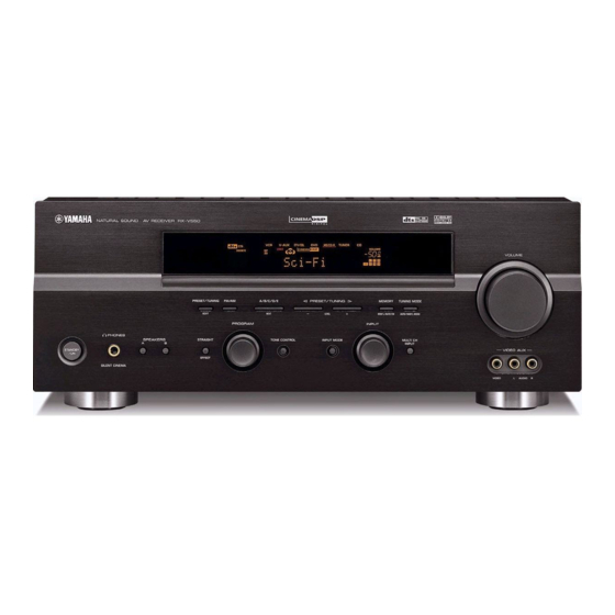
Yamaha HTR-5750 Service-Handbuch - Seite 21
Blättern Sie online oder laden Sie pdf Service-Handbuch für Empfänger Yamaha HTR-5750 herunter. Yamaha HTR-5750 39 Seiten. Av receiver/av amplifier

- 1. Contents
- 2. Service Manual
- 3. Set Menu Table
- 4. Internal View
- 5. Block Diagram
- 6. Printed Circuit Board (Foil Side)
- 7. Schematic Diagram
- 8. Schematic Diagram (Operation)
- 9. Schematic Diagram (Main)
- 10. Schematic Diagram (Power)
- 11. Schematic Diagram (Subtrans)
- 12. Schematic Diagram (Video)
- 13. Exploded View
A
B
I
1
OPERATION (1) P. C. B. (Surface Mount Device)
2
3
4
Circuit No.
R836-839
X: NOT USED
O: USED / APPLICABLE
5
• Semiconductor Location
Ref. no. Location
D0801
I2
6
D0802
H2
D0803
D0871
D6
D0872
D7
D0873
D7
D0881
F6
D0882
F6
D0883
F6
D0884
F6
IC801
F3
Q0801
F2
Q0802
F2
Q0803
H3
7
Q0804
H3
Q0805
H3
Q0806
G3
C
D
HTR-5750
RX-V450/HTR-5740/DSP-AX450
J, U, C, A, L, R, T, K B, G, E
X
O
OPERATION (3) P. C. B.
(Surface Mount Device)
E
F
G
33
32
48
17
49
16
64
1
OPERATION (4) P. C. B.
(Surface Mount Device)
H
I
J
RX-V550/HTR-5750
RX-V450/HTR-5740/DSP-AX450
OPERATION (5) P. C. B.
(Surface Mount Device)
69
