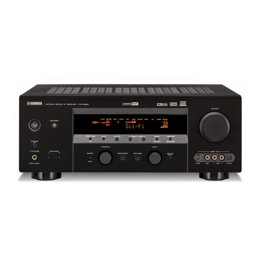
Yamaha htr-5890 Service-Handbuch - Seite 9
Blättern Sie online oder laden Sie pdf Service-Handbuch für Empfänger Yamaha htr-5890 herunter. Yamaha htr-5890 41 Seiten.

- 1. Table of Contents
- 2. Service Manual
- 3. Important Notice
- 4. To Service Personnel
- 5. Front Panel
- 6. Remote Control Panel
- 7. Rear Panels
- 8. Specifications
- 9. Internal View
- 10. Disassembly Procedures
- 11. Updating Firmware
- 12. Self Diagnosis Function (Diag)
- 13. Amp Adjustment
- 14. Display Data
- 15. IC Data
- 16. Remote Control
I DISASSEMBLY PROCEDURES
(Remove parts in the order as numbered.)
Disconnect the power cable from the AC outlet.
1. Removal of Top Cover
a. Remove 2 screws (1), 4 screws (2) and 5 screws (3).
(Fig. 1)
b. Slide the Top Cover rearward to remove it. (Fig. 1)
Front Panel Unit
4
CB25
2
4
A
CB863
2. Removal of Front Panel Unit
a. Remove 9 screws (4) and then slide the Front Panel
Unit forward. (Fig. 1)
b. Remove CB25, CB505, CB509, CB512, CB861 ~
CB863 and then remove the Front Panel Unit. (Fig. 2)
3
1
Top Cover
2
4
Fig. 1
FUNCTION P.C.B.
CB509
CB505
CB861
CB862
Fig. 2
HTR-5890
3
CB512
View A
9
