aldes 11071139 Installationsanleitung Handbuch - Seite 3
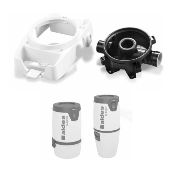
Blättern Sie online oder laden Sie pdf Installationsanleitung Handbuch für Staubsauger aldes 11071139 herunter. aldes 11071139 8 Seiten. Wall bracket for c.axpir initia & c.axpir comfort

1
2/3
4/5
6/7
8
FR
1. Assurez-vous que les côtés entrée et sortie de la tuyauterie menant à la centrale se trouvent
du bon côté du berceau mural.
La partie intérieure du berceau mural peut être installée dans les deux sens.
2. Alignez la partie intérieure du berceau mural verticalement sur le mur, avec une déviation
maximale de +-5 degrés.
3. Fixez solidement la partie intérieure du berceau mural à la structure du mur à l'aide de vis
(4,2x50 mm TX20). Utilisez des chevilles si nécessaire (chevilles 6 x 30).
4. Branchez les fils basse tension sur le connecteur du berceau mural conformément
au tableau ci-dessous.
1
2
3
4
5
6
Pour l'installation standard, seules les raccordements des fils basse tension (n°4 et n°5) sont
utilisés. C.Axpir
Initia doit être raccordé aux prises d'aspiration. C.Axpir
®
fonctionne sans fil et n'a besoin d'une connexion câblée que dans le cas d'une plinthe
ramasse-miettes.
5. Connectez le connecteur basse tension au cadre extérieur du berceau mural.
6. Placez le cadre extérieur du berceau mural verticalement sur la partie
intérieure du berceau mural.
7. Fixez solidement la cadre extérieur du berceau mural à la partie intérieure à l'aide de vis
(5x20 mm TX20).
8. Utilisez les pattes de fixation sur le cadre extérieur du berceau mural pour une fixation
supplémentaire, si nécessaire. (En cas de montage sur un poteau de cloison, par exemple.
Vis non comprises dans la livraison).
EN
1. Make sure that the input and output sides of the piping leading to the central unit are on
the correct sides of the wall bracket. The inner part of the wall bracket can be
installed either way around.
2. Align the inner part of the wall bracket vertically on the wall, with a maximum
deviation of +-5 degrees.
3. Attach the inner part of the wall bracket securely to the wall structure with screws (4,2x50
mm TX20). Use the wall plug if necessary (wall plug 6 x 30).
4. Connect the low voltage wires to the wall bracket's connector in accordance with the table below.
1
2
3
4
5
6/7/8
For standard installation, only the low voltage wires connections (#4 and #5) are used.
C.Axpir
Initia must be wired to inlet valves. C.Axpir
®
a wired connection in the case of a crumb plinth.
5. Connect the low voltage connector to the outer frame of the wall bracket
6. Place the outer frame of the wall bracket vertically on top of the inner part
of the wall bracket.
7. Attach the outer frame of the wall bracket to the inner part with screws (5x20 mm TX20).
8. Use the mounting lugs on the outer frame of the wall bracket for additional fastening, if
necessary. (If mounting on a partition wall stud, for example.
Screws not included in delivery.)
GND
Terre. Ne pas utiliser.
AHU1
Contact sec hors tension 24 Vca/cc 1 A. (C.Axpir
AHU2
Contact sec hors tension 24 Vca/cc 1 A. (C.Axpir
SW2
Câbles basse tension (contrôle de la prise d'aspiration)
SW1
Câbles basse tension (contrôle de la prise d'aspiration)
N/A
Ne pas utiliser
GND
Ground. Do not use.
AHU1
Voltage free contact 24 VAC/DC 1 A. (C.Axpir
AHU2
Voltage free contact 24 VAC/DC 1 A. (C.Axpir
SW2
Low voltage wires (wall inlet control)
SW1
Low voltage wires (wall inlet control)
N/A
Do not use.
Comfort works wireless and only needs
®
Initia uniquement)
®
Initia uniquement)
®
Comfort
®
Initia only)
®
Initia only)
®
3
