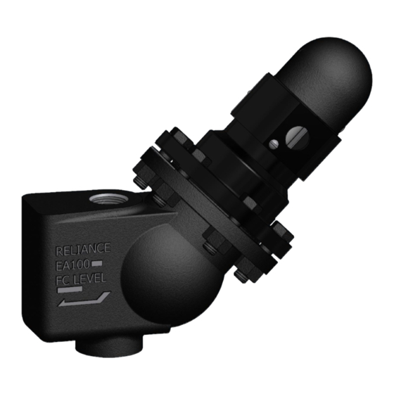
Clark-Reliance Levalarm EA100DP Anweisungen für Installation und Betrieb - Seite 3
Blättern Sie online oder laden Sie pdf Anweisungen für Installation und Betrieb für Industrielle Ausrüstung Clark-Reliance Levalarm EA100DP herunter. Clark-Reliance Levalarm EA100DP 10 Seiten.

Standard connections for the EA100 Series Levalarms are 1" FNPT for threaded connections or 1"
FSW for socket weld connections. The Levalarm should be installed with the reference arrow (switch
point) at the level where the alarm or trip is specified. Shut off valves above and below the Levalarm
should be installed for safe inspection or repair of the unit. However, these valves must be locked
open when the boiler is in service.. Also, a drain connection with a shut off valve should be installed
to a point of safe discharge to facilitate blowdowns. Below is a typical arrangement for the installation
of the Levalarm.
After the piping has been installed to the body of the Levelarm, the switch should connected by
following this procedure:
1. Remove the switch cover in order to access the connections on the switch assembly by
loosening the screw ot the bottom of the dome shaped cover.
2. Use the 7/8" Dia. opening in the switch housing assembly for connecting flexible or rigid
conduit when wiring the unit.
3. Example wiring diagrams for connectiong the low water cutout, alarms (such as lights or and
audible signal), etc, are illustrated below.
4. After checking that all connections are tight and correct, replace the switch cover, as the unit is
now ready do be put in operation.
Low Water Cutout Level
Note: Some jurisdictions do not permit the
installation of isolation valves as shown.
Consult applicable Codes before installation.
