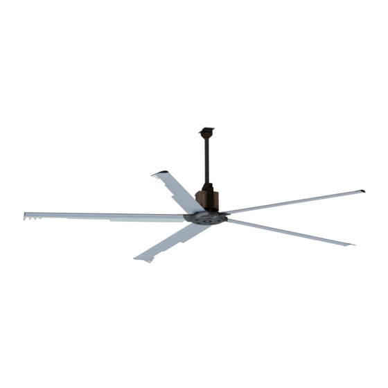
aerauliqa WHS500 Handbuch - Seite 17
Blättern Sie online oder laden Sie pdf Handbuch für Fan aerauliqa WHS500 herunter. aerauliqa WHS500 20 Seiten.

9.3 CONTROL WITH EXTERNAL POTENTIOMETER (not supplied)
WARNING: regardless of the control system in place (potentiometer or Modbus), it's strongly recommended to wire
the Modbus communication line and make it accessible from ground level, in order to ease troubleshooting via
Modbus anytime after the installation.
10. CLEANING
The unit (IP55) can be washed with water jets. In this case it is recommended to drill a hole under the plastic hub cover for water
drainage.
11. TROUBLESHOOTING (Modbus)
11.1 Connection parameters
11.2 Modbus Registers - Input Register
These registers are READ-ONLY, and can be read using the function 04 READ INPUT REGISTERS.
Register
Description
Address
3
Measured speed
10
Alarm 1
17
Alarm 2
L3
4-core power cable
L2
L1
4-core power cable
6-core control cable
PT02
PT01
NO
NC
6-core control cable
COM
GND
+10Vout
GND
Vin 2
Vin 1
COMMON
IN 4A
IN 3A
IN 2A
IN 1A
TERM
485 +
TERM
485 -
SCH
GND-iso
Protocol
Baud Rate (bps)
Data bits
Parity bits
Stop bits
HVLS Slave Address
Dimension
Data
(Word)
Type
1
ushort
1
ushort
1
ushort
YELLOW - GREEN
BROWN
L3
L1
3 ph.
POWER
L2
BLACK
3 ph.
SUPPLY
L2
POWER
GREY
L1
L3
SUPPLY
YELLOW - GREEN
BROWN
BROWN
L1
3 ph.
POWER
YELLOW
BLACK
SUPPLY
L2
GREEN
GREY
L3
WHITE
MODBUS B
BROWN
GREY
MODBUS A
YELLOW
PINK
GREEN
WHITE
MODBUS B
GREY
MODBUS A
PINK
MODBUS/RTU over RS485
9600
8
none
2
1
U.M. (data on
the register)
0.1rpm
-
-
17
EXTERNAL
POTENTIOMETER
≥10kΩ
(NOT SUPPLIED)
EXTERNAL
EXTERNAL
POTENTIOMETER
POTENTIOMETER
≥10kΩ
≥10kΩ
(NOT SUPPLIED)
(NOT SUPPLIED)
Example
Register value → Real value
490 → 49rpm
See table (§ 11.3)
See table (§ 11.3)
