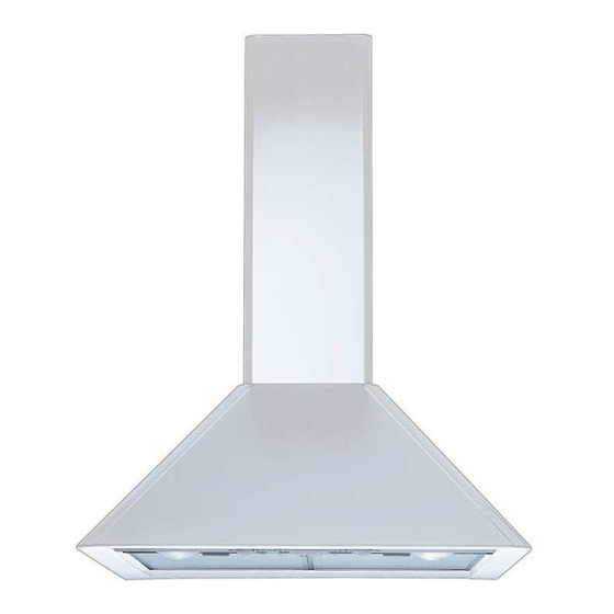
Zanussi ZHC 915 Handbuch für Installation, Nutzung und Wartung - Seite 8
Blättern Sie online oder laden Sie pdf Handbuch für Installation, Nutzung und Wartung für Lüftungshaube Zanussi ZHC 915 herunter. Zanussi ZHC 915 18 Seiten.

d) Chimney hood with grilles: once the chimney stack has been installed, fit the two venting
grilles into the apertures located on either side of the lower chimney section. The grilles are
marked with two arrows and should be fitted with one arrow pointing upwards and the other
toward the front. When the hood is used in the recirculation mode ensure that the grilles are
properly secured to the recirculation spigot item R, as illustrated in fig. 9.
a
Part 2
OPERATION AND MAINTENANCE INSTRUCTIONS
1 - Safety warnings
It is most important that all the warnings shown in paragraph 3 of the Installation
Instructions are strictly observed. Moreover, pay special attention to the following warnings
during the use and maintenance of the cooker hood:
1.1- The grease filters and the charcoal filter should be cleaned or replaced as
recommended by the manufacturer or more frequently if the hood is used consistently
over 4 hours per day.
1.2- When using a gas hob in connection with the cooker hood never leave the burners of
the hob uncovered while the hood is in use or when the pans have been removed.
Switch off the gas before removing the pan, or for just short periods and never leave
the hob unattended.
1.3- Always ensure that the flame is kept at the correct intensity to prevent the flame from
licking round from the bottom of the pan; this will save energy and will avoid a
dangerous concentration of heat.
1.4- Always ensure that the appliance is used in accordance with the manufacturer's
instructions for the removal of contaminated air and odours during cooking.
2 - OPERATION
1 - Switch control panel (fig. 10)
The cooker hood can be operated as follows:
SWITCH L=
controls the worktop illumination;
SWITCH M
= controls the power to the motor;
SWITCH V=
controls the fan speed:
Position 1 =
low speed, should be selected when simmering or using only one pan;
the noise level is kept to the minimun.
Position 2 =
medium speed, should be selected for normal cooking. This speed offers
the best ratio between air capacity and noise level.
Position 3 =
top speed, should be selected when frying or cooking food with strong
odours, even for a long period.
2 - Button control panel (fig. 11)
The layout of the control is as follows:
BUTTON L
= Turns the lighting system on and off;
BUTTON V1
= Turns the on and off at low speed. This is ideal to obtain a particularly
silent but continuous flow of air when the level of cooking fumes is low;
BUTTON V2
= Medium speed, suitable for most normal operating conditions. This gives an
excellent ratio between treated air flow and noise level;
BUTTON V3
= High speed, suitable to deal with heavy cooking fumes, even for long periods of
time.
13
