Clarke VVE11A150 Betriebs- und Wartungsanleitung - Seite 7
Blättern Sie online oder laden Sie pdf Betriebs- und Wartungsanleitung für Luftkompressor Clarke VVE11A150 herunter. Clarke VVE11A150 16 Seiten. Air compressor electric motor driven
Auch für Clarke VVE11A150: Handbuch für Betrieb und Wartung (17 seiten)

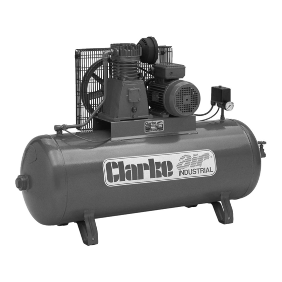
GENERAL ARRANGEMENT
A. STATIONARY
NB: Must be mounted on anti-vibration pads.
1. Air Compressor Pump 8.
2. Electric Motor
(or petrol/diesel engine) 10. Non-Return Valve
3. Wire Guard
4. Pressure Switch
5. Pressure Gauge
6. Safety Valve
7. Ball Valve
NOTES:
1.
On automatic machines 10 H.P. & above a solenoid valve is fitted to the
delivery pipe.
2.
On automatic machines 10 H.P. & above, an Auto Star Delta (ASD) starter is
fitted, ready to be mounted to a wall or panel etc. It is IMPORTANT to note
that NO ADJUSTMENTS should be made to this component.
The ASD should be connected to a 3-phase supply by a qualified electrician.
Drain Tap
9.
Inspection Plug
11. Air Bleed Valve
12. Oil Drain Plug
13. Saddle
14. Air Intake Filter
15. Oil Filler/Breather
7
Fig.2
16. Oil Level Sight Glass
17. –
18. –
19. Air Delivery Pipe
20. Air Bleed Pipe
21. Air Receiver
22. On/Off switch
23. Auto Air Bleed
Illustrative
purposes only
