Directed Xpresskit DBALL2 Installationshandbuch - Seite 4

Blättern Sie online oder laden Sie pdf Installationshandbuch für Durch Schlösser Directed Xpresskit DBALL2 herunter. Directed Xpresskit DBALL2 16 Seiten. Ford5 remote start ready (rsr) installation
Auch für Directed Xpresskit DBALL2: Installationshandbuch (12 seiten), Installationshandbuch (19 seiten), Installationshandbuch (18 seiten), Handbuch (14 seiten), Installationshandbuch (13 seiten), Installationshandbuch (14 seiten), Installationshandbuch (19 seiten), Installationshandbuch (16 seiten), Installationshandbuch (20 seiten), Installationshandbuch (15 seiten), Handbuch für Installation und Kurzanleitung (16 seiten), Installationshandbuch (18 seiten), Installationshandbuch (16 seiten), Installationshandbuch (18 seiten), Handbuch (19 seiten)
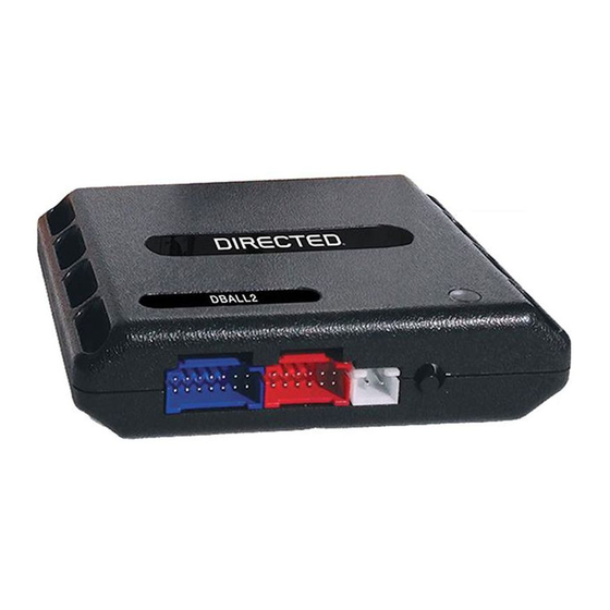
Directed Xpresskit DBALL2 Installationshandbuch
Platform: DBALL2
Firmware:
CHRYSLER4
Type 1 -
Vehicle
Wiring Reference Chart
Wire Information
Function
Color
Chrysler Town & Country 2004-2007
Starter
Yellow
Ignition
Pink/White
MUX Starter/Ignition Violet/Brown
12V
Violet/Red
J1850
White/Violet
Immo. Ignition
Pink/White or Pink/Gray
Parking Lights
White/Brown or White/Orange
Driver Door Trigger
Violet
Dodge Caravan 2004-2007
Starter
Yellow
Ignition
Pink/White
MUX Starter/Ignition Violet/Brown
12V
Violet/Red
J1850
White/Violet
Immo. Ignition
Pink/White
Parking Lights
White/Orange
Driver Door Trigger
Violet
Dodge Grand Caravan 2004-2007
Starter
Yellow
Ignition
Pink/White or Pink/Gray
MUX Starter/Ignition Violet/Brown
12V
Violet/Red
J1850
White/Violet
Immo. Ignition
Pink/White
Parking Lights
White/Orange
Driver Door Trigger
Violet
Pin
Polarity Location
4
(+)
Ignition switch.
3
(+)
Ignition switch.
2
MUX
Ignition switch.
5
(+)
Top connector to BCM.
2
Data
SKIM (Sentry Key Immobilizer Module) Black
4
CUT
SKIM (Sentry Key Immobilizer Module) Black
N/A
(+)
Driver kick panel.
6
(-)
Third connector from top of BCM.
4
(+)
Ignition switch.
3
(+)
Ignition switch.
2
MUX
Ignition switch.
5
(+)
Top connector to BCM.
2
Data
SKIM (Sentry Key Immobilizer Module) Black
4
CUT
SKIM (Sentry Key Immobilizer Module) Black
N/A
(+)
Driver kick panel.
6
(-)
Third connector from top of BCM.
4
(+)
Ignition switch.
3
(+)
Ignition switch.
2
MUX
Ignition switch.
5
(+)
Top connector to BCM.
2
Data
SKIM (Sentry Key Immobilizer Module) Black
4
CUT
SKIM (Sentry Key Immobilizer Module) Black
N/A
(+)
Driver kick panel.
6
(-)
Third connector from top of BCM.
Rev.: 20170818
Connector Information
Color
Black
Black
Black
Black
N/A
Black
Black
Black
Black
Black
N/A
Black
Black
Black
Black
Black
N/A
Black
© 2017 Directed. All rights reserved.
Page 4
Pins
5
5
5
6
6
6
N/A
34
5
5
5
6
6
6
N/A
34
5
5
5
6
6
6
N/A
34