Directed Xpresskit DBALL2 Installationshandbuch - Seite 7

Blättern Sie online oder laden Sie pdf Installationshandbuch für Durch Schlösser Directed Xpresskit DBALL2 herunter. Directed Xpresskit DBALL2 16 Seiten. Ford5 remote start ready (rsr) installation
Auch für Directed Xpresskit DBALL2: Installationshandbuch (12 seiten), Installationshandbuch (19 seiten), Installationshandbuch (18 seiten), Handbuch (14 seiten), Installationshandbuch (13 seiten), Installationshandbuch (14 seiten), Installationshandbuch (19 seiten), Installationshandbuch (16 seiten), Installationshandbuch (20 seiten), Installationshandbuch (15 seiten), Handbuch für Installation und Kurzanleitung (16 seiten), Installationshandbuch (18 seiten), Installationshandbuch (16 seiten), Installationshandbuch (18 seiten), Handbuch (19 seiten)
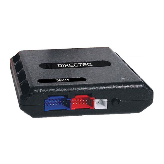
Directed Xpresskit DBALL2 Installationshandbuch
Platform: DBALL2
Firmware:
CHRYSLER4
Installation Type 3
BCM
(
Gray
conn. bottom of BCM)
11
10
9
8
7
6
22
21
20
19
18
17
920Ω
85
86
87
( ) + 12V
87a
30
Sentry Key
J1850:
(+) Ignition:
White/Violet,
Pink/Lt. Green
,
pin 2
pin 4
Module-Sentry Key
6
1
Remote Entry
Not required in D2D mode.
Tach wire is an optional connection required on some remote starters, which do not support a tach signal in D2D.
[1]
All adapters are displayed from the wire side (unless specified otherwise).
2
1
5
4
3
13
12
16
15
14
(-) Parking Lights:
Pink/Red
, pin 5
(-) Parking Lights Output
(-) Trunk Status Input
(-) Door Status Input
J1850:
Violet/Yellow:
Ignition Interrupt (
vehicle side
):
Yellow:
Ignition Interrupt (
conn. side
):
Orange/Yellow:
(+) 12V
(+) 12V Input:
Red:
(-) Ground
(-) Ground:
Black:
(-) RAP Off Output:
Black/White:
(-) Door Status Output:
Green/White
(-) Trunk Status Output:
Red/Black:
(
AC
) Tach Output:
Violet/White
[1]
(+) Brake Output:
Gray:
(+) 12V:
Ignition Switch
(black
(+) 12V Input
(+) Brake Input
(
AC
) Tach Input
[1]
2
8
9
13
14
1
: 3
4
: 5
6
RF
DBALL/
Prog. button
DBALL
LED
(+) Starter:
Lt. Blue/Red
Red
, pin 1
1
2
3
4
5
connector
)
6
7
8
9
10
Pink/Yellow,
Pink/
pin 7
Yellow, pin 8
(+) Accessory 2 Output
(+) Accessory 1 Output
(-)
Lock
Output
(-)
Unlock
Output
(+) Starter Output
(+) Ignition
In
put
(-)
GWR
(Status) Output
10:
Blue/White:
(-)
GWR
(Status) Input
9:
Pink:
(+) Ignition Input
8:
Violet:
(+) Starter Input
2:
Blue:
(-) Unlock Input
1:
Green:
(-) Lock Input
(+)12V
RX
(-) Ground
2
TX
P#:
XKD
2D65
BCM
(
Gray conn. top of BCM
)
© 2017 Directed. All rights reserved.
Rev.: 20170818
Page 7
, pin 6
(+) Ignition: Pink/
Lt. Green, pin 2
(-) Drivers Door
Trigger:
Violet
,
pin 4