Alemite 8549-C Service-Handbuch - Seite 10
Blättern Sie online oder laden Sie pdf Service-Handbuch für Water Pump Alemite 8549-C herunter. Alemite 8549-C 13 Seiten.
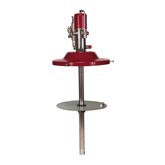
SER 8540-B
CAUTION
Install the outer component assembly onto the inner assembly
with care. Damage to Seal (29) can occur.
24 Install the outer component assembly onto the inner assembly.
•
Use a slight twisting motion to pass the Seal
•
At the same time thread the Adapter into the base of the air
motor.
IMPORTANT: Make sure the flange portion of the Adapter seats
flush against the base of the air motor. Should a gap exist, inspect
the components of the air motor packing group.
25 Install Stop Washer (33) into the Extension.
26 Install and seat Seal (34) [heel end first] into Valve Body (35).
27 Install the Valve Body assembly (Seal first) onto Rod (37).
•
Make sure the Valve Body assembly seats properly in the
Extension.
28 Install Follower Tube (41) over the outer tube assembly.
29 Install O-Ring (42) onto Primer Body (43).
30 Install and seat Valve Seat (36) [large diameter first] into the
Primer Body.
31 Install and seat Gasket (14) into the Primer Body.
32 Screw the Primer Body onto the Extension.
33 Place a large wrench or other suitable tool into the slot of the
Primer Body.
•
Tighten all the components of the assembly securely.
•
Crush all Gaskets.
34 Extend Rod (37) from the Primer Body.
•
Apply air to the motor as necessary.
35 Install Primer Disc (39) onto the Rod.
36 Gently screw Nut (40) onto the Rod.
•
Use an appropriate size punch in the hole of the Rod to prevent
rotation. See Figure 2.
•
Do not overtighten.
Model Dependent Step
37 Install Bung Adapter (44) onto the Follower Tube.
model8549-Bl].
Pressurtrol
Screw Fitting (9) [with thread sealant] and Angle Body (6) [with
thread sealant] into the Pressurtrol.
•
Tighten each component securely.
•
Make sure to orient the components properly.
38 Screw Air Connector (7) [with thread sealant] into the Angle
Body.
•
Tighten the Air Connector securely.
39 Screw Adapter (4) [with thread sealant] into Air Motor (3).
•
Tighten the Adapter securely.
40 Screw Pressurtrol (5) onto the Adapter [with thread sealant].
IMPORTANT: Tighten the Pressurtrol just short of vertical. This
allows the assembly of Tube (11).
41 Screw Adapter (10) into the Air Motor.
•
Tighten the Adapter securely.
•
Make sure to orient the Adapter properly.
42 Screw additional Fitting (9) into the Adapter.
•
Tighten the Fitting securely.
•
Make sure to orient the Fitting properly.
43 Position Tube (11) into each Fitting.
44 Secure the Tube by rotating the Pressurtrol to vertical.
•
Tighten the Fittings to the Tube.
45 Install Air Coupler (8) onto the Air Connector.
Operation
WARNING
Do not exceed the lowest pressure rating of any
component in the system.
Do not alter the design of the pump. Never install addition-
al components to the outlet of the pressurtrol.
Never point a control valve at any portion of your body or
another person. Lubricant discharged at high velocity can
penetrate the skin and cause severe injury. Should any flu-
id appear to puncture the skin, get medical care
immediately.
Ensure all components are in operable condition. Replace
any suspect parts prior to operation. Personal injury can
occur.
1 Make sure air pressure at the regulator reads zero.
2 Slowly supply air pressure [not to exceed 20 psi (1.4 Bars)] to the
pump's motor.
•
The pump assembly should cycle.
If the pump assembly does not cycle, refer to the Troubleshooting
Chart for details.
With air pressure at zero:
3 Connect a product hose to the pressurtrol's material outlet.
•
Direct the hose into an appropriate collection container.
4 Place the pump in grease.
5 Slowly supply air pressure to the pump's motor.
6 Allow the pump to cycle slowly until the system and grease is free
of air.
If the pump assembly does not prime, refer to the Troubleshooting
Chart for details.
10
High Pressure Lubricant Pump