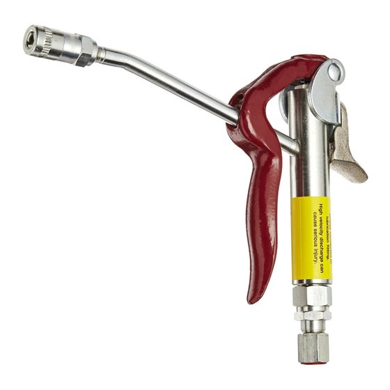
Alemite 6320-3 Service-Handbuch - Seite 7
Blättern Sie online oder laden Sie pdf Service-Handbuch für Kontrolleinheit Alemite 6320-3 herunter. Alemite 6320-3 10 Seiten. High-pressure control valve

High-Pressure Control Valve
6. Spring (13) onto the Stem.
7. Aluminum crush Gasket (14) into the Body.
8. Symmetrical Guide (15) and additional Gasket (14).
9. Valve and Seat Assembly (16) and final Gasket (14)
into the Body.
10. Bushing (17) into the Body.
• While retaining Packing Plug ( 3 ), tighten Bushing
(17) securely into the Body. Tighten sufficiently to
properly crush Gaskets (14).
N O T E : M a k e s u r e P l u n g e r St e m ( 11 )
extends approximately 3/8 " (9.5 mm) from
top of Body (10) and has spring pressure. If
no pressure is felt, Washer (12) is installed
incorrectly. Refer to steps 3 and 4.
11. Setscrew (1) into Lever and Bracket assembly (2).
12. Position the top of the Setscrew so one full thread on
the Lever and Bracket assembly is present.
See Figure 2.
13. Lever and Bracket assembly and Support (9) onto the
Body.
14. Lock Washer (7) and Screw (8).
• Tighten screw securely.
15. Extension (25) and Coupler (26) into the Body.
• Tighten the extension in the proper position.
CAUTION
Do not use excessive force when installing Single-
Shot Adjuster (24) into Bushing (17). Component
damage can occur.
16. Single-Shot Adjuster (24) into Bushing (17) until it
seats against the Spring and Plunger Seat
assembly (16).
IMPORTANT: Turn the Single-Shot Adjuster
c o u n t e r c l o c k w i s e 1 - 1 / 4 t u r n s . T h i s
a d j u s t m e n t a p p ro x i m a t e s t h e s e t t i n g
re q u i re d f o r t h e s i n g l e - s h o t m o d e - o f -
operation.
17. Packing Ring (21) into Bushing (17).
18. Locknut (20) onto Single-Shot Adjuster (24) firmly.
• Make sure the Single-Shot Adjuster does not move
from initial setting of 1-1/4 turns.
Alemite LLC
19. Single-Shot Valve (23) and Spring (22) into the
Single-Shot Adjuster.
• Make sure the Single-Shot Valve is centered
properly.
20. Gasket (19) into the Single-Shot Adjuster.
IMPORTANT: Press downward on Inlet
A d a p t e r ( 1 8 ) d u r i n g i n s t a l l a t i o n t o
overcome Spring pressure. Cross threading
can occur.
21. Inlet Adapter (18) into the Single-Shot Adjuster.
• Tighten sufficiently to properly crush the Gasket.
Setscrew Adjustment (Lever Free-Play)
IMPORTANT: This setting establishes the
amount of lever travel before the single-shot
mode-of-operation takes effect.
If the clearance is too great, the continuous
mode-of-operation can be lost. Not enough
clearance can prevent the valve from shutting
off.
The setscrew should be adjusted so a 1/16 " (1.5 mm)
clearance between the bottom of the hole on Lever (2) and
the surface of Extension (25) is achieved. See Figure 4.
2
1/16 "
(1.5 mm)
Figure 4 Lever Free-Play
This setting is the amount of lever free-play before
product begins to flow.
To set the clearance, adjust Setscrew (1) clockwise to
increase the amount of free-play or counterclockwise to
decrease the gap.
7
SER 6320-3
1
25
Revision (1-13)
