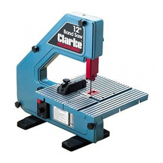
Clarke Woodworker CBS12WV Betriebs- und Wartungshandbuch - Seite 11
Blättern Sie online oder laden Sie pdf Betriebs- und Wartungshandbuch für Säge Clarke Woodworker CBS12WV herunter. Clarke Woodworker CBS12WV 16 Seiten. 305mm (12”) portable bandsaw

OPERATION
WARNING! Make sure the bandsaw is correctly assembled and adjusted
before use. Read and follow all safety instructions (see page 3)
•
The blade supplied with the saw is suitable for general purpose cutting of hard and soft
woods . It is not suitable for cutting metals (See restrictions of use, page 3). The speed of
the bandsaw can be adjusted to suit the material by using the control knob below the
on/off switch. Use slower speeds for harder materials.
•
A dust extractor may be used during use. Simply connect a suitable hose (not supplied),
from the dust extractor, to the dust extractor port (23, Fig.3). Dust Extractors are available
from your Clarke dealer.
•
The saw is supplied with a mitre gauge to allow mitre cuts to be made.
Set the gauge to the desired angle, and use the guide slot in the table to run the mitre
gauge with the workpiece across the table, into the blade as shown in Fig. 6 .
•
The mitre gauge can also be used as a rip fence by placing it in the slot at right angles
to the blade. Fix it into place at the desired distance from the blade by using the
countersunk screw in the slot. When using the mitre gauge as a rip fence you may wish
to screw a suitable piece of hardwood or plywood (approximately 300 x 75 x 12 mm) to
the face of the gauge to extend its length (fig 7).
•
The saw table can be tilted up to 45 degrees to allow you to cut bevels and compound
mitres. Slacken the table securing knobs, position the table to the desired angle, as
shown on the scale beneath the table, and tighten the knobs (see fig 3).
NOTE: If accurate mitres are required, check the table angle using a suitable gauge between
the table and blade. When adjusted, check to ensure the pointer is indicating the correct
angle and adjust if necessary.
Fig. (6) Using the Mitre Gauge
Mitre Gauge
31
Mitre Gauge Slot
32
31
32
11
Figure (7) Using as a Rip Fence
33
Option Rip Fence Extension
33
Rip Fence Fixing Screw
34
34
