CTS IES-3006SFP-F1-DR Handbuch - Seite 13
Blättern Sie online oder laden Sie pdf Handbuch für Schalter CTS IES-3006SFP-F1-DR herunter. CTS IES-3006SFP-F1-DR 16 Seiten. Industrial ethernet switch
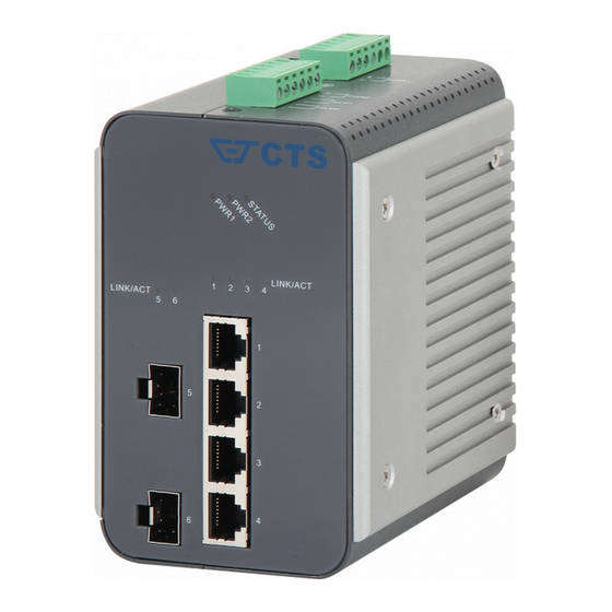
2.5 Wiring the Alarm Contact
The Industrial Ethernet Switch has two sets of Alarm Contacts which are used to detect
both power faults and port faults. We will explain the meaning of the two sets of
contacts used to connect the Alarm Contact below.
If you have
two
Alarm Systems:
If you have
only one
(series connection)
STEP 1 :
Insert the negative/positive DC wires into the V-/V+
terminals.
STEP 2 :
Use a small flat-blade screwdriver to tighten the
wire-clamp screws on the front of the terminal block
connector.
STEP 3 :
Insert the plastic terminal block connector prongs into the
terminal block receptor, which is located on the IES's top
panel.
ALM1:
The two wires attached to the Fault contacts form an
open circuit when the IES has lost power from one of the
DC power inputs.
ALM 2 :
The two wires attached to the Fault contacts form an
open circuit when one of the ports for which the
corresponding Port Alarm DIP Switch is set to ON be
not properly connected.
Alarm System:
The two wires attached to the Fault contacts form an
open circuit when :
The IES has lost power from one of the DC power
inputs.
AND
One of the ports for which the corresponding Port Alarm
DIP Switch is set to ON be not properly connected.
13