Armstrong 4600 HSC series Installations- und Betriebsanleitung - Seite 10
Blättern Sie online oder laden Sie pdf Installations- und Betriebsanleitung für Water Pump Armstrong 4600 HSC series herunter. Armstrong 4600 HSC series 16 Seiten. Horizontal split case fire pumps. 12x8x18f

i n s ta l l at i o n &
o p e r at i n g i n s t r u c t i o n s
10
3.2. bearings
• sealed greased for life bearings are fitted on your pump.
• No particular attention is required
• No need for greasing since the bearings are greased for the
entire bearing life
• If abnormal noises come from the bearing during normal
operation, replace bearings
3.3. stuffing box with packing
stuffing box dismantling
• Adjust pressure of packing gland to obtain a slight leak of 6
to 8 drops per minute for suction pressures up to 20 psig (the
increase in suction pressure causes proportional increase in
leakage through the stuffing box)
• Remove flush line connection from stuffing box extension
• Remove gland plate from stuffing box
• Remove stuffing box extension
packing replacement
• When removing old packing, make sure bottom rings are
completely removed
• Thoroughly clean the stuffing box and check condition of
shaft sleeve (a badly worn or corroded shaft sleeve will never
seal properly)
• Cut packing into lengths allowing V" between ends when
installed
• Place first ring around shaft and press firmly and evenly into
stuffing box
• Continue in the same manner staggering ring joints one quar-
ter of a turn until stuffing box is filled
• Make certain lantern ring is in correct position under
pipe connection
stuffing box assembly
• Install back stuffing box extension
• Install flush line connection on stuffing box extension
• Install gland plate and compress evenly leaving it finger tight
• Compress packing evenly with gland and leave gland nut
finger tight
• With pump running adjust gland with recommended
leakage rate
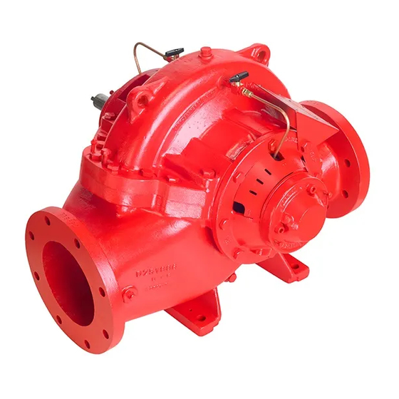
Horizontal split case
fire pumps
caution: Packing should not be pressed too tight, as this
may result in burning the packing and scoring the shaft
sleeve.
4.0 pump disassembly
warning: Whenever any disassembly work is to be done
on pump, disconnect power source to driver to eliminate
any possibility of starting unit.
4.1
to remove rotating assembly
1. Remove coupling guard and disconnect coupling halves
2. Disconnect flush line from upper half casing
3. Remove bolting from bearing covers and jack the (2) screws
to help remove bearing covers
4. Remove bearing locknut on opposite side of motor
5. Remove bearing by holding shaft in place and turning nut
behind bearing; bearing will slide out
6. Remove gland plate and split gland
7. Remove stuffing box extension
8. Remove packing, lantern ring and bushing
9. Remove top casing bolting
10. Screw (2) jack screws down to separate upper and
lower case
11. Turn jack screws back after separation to prevent interfer-
ence at reassembly
12. Lift upper casing straight up until clear of impeller
13. Place slings around shaft near the bearing housings and lift
shaft assembly
14. Place shaft assembly in a clean, dry work area for necessary
disassembly
4.2 disassembly of rotating element
1. Remove pump half coupling
2. Unscrew (4) setscrews in sleeve, then unscrew sleeve on
right side of the pump when facing suction flange
3. Slide impeller on shaft and remove
note direction of vanes. impeller must be installed in
same direction.
4. Remove impeller key
5. Unscrew other sleeve
