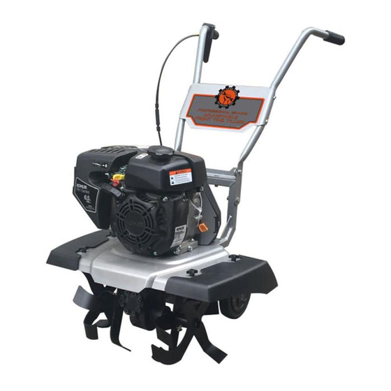
DIRTY HANDS 107555 Betriebshandbuch - Seite 10
Blättern Sie online oder laden Sie pdf Betriebshandbuch für Pinne DIRTY HANDS 107555 herunter. DIRTY HANDS 107555 20 Seiten. 14”-22” adjustable front tine tiller

Handlebar Assembly
Mounting the Handlebars
NOTE: The left and right handlebars are different. Each has two holes
drilled in the bottom of the handlebar tube and two more drilled in the
middle.
1. Install the upper handlebar bracket to the square tubing of the frame
using two M8x40mm bolts and nyloc nuts and two 13mm wrenches
in the configuration shown in
2. Position the right and left handlebars with the grips facing outwards.
Align the two lower holes in the frame and upper handlebar bracket.
Install the M10x25mm and M10x50mm bolts as shown in Figure 2
and hand tighten.
3. Mount the handlebar bridge using four M8x40mm bolts and nyloc
nuts to the middle holes in the handlebars using two 13mm wrenches.
4. Finish tightening the lower M10 bolts and nyloc nuts using two
17mm wrenches.
5. Use the supplied zip ties to secure the cable from the clutch handle to
the handlebars and tiller frame.
LEFT
HANDLEBAR
M10 x 25mm
M8 x 40mm
M10 x 50mm
FRAME
LEFT
TINE GUARD
10
Figure 2.
HANDLEBAR
BRIDGE
RIGHT
HANDLEBAR
M8 x 40mm
UPPER HANDLEBAR
BRACKET
Figure 2
PLASTIC WINGED
NUTS
RIGHT
TINE GUARD
