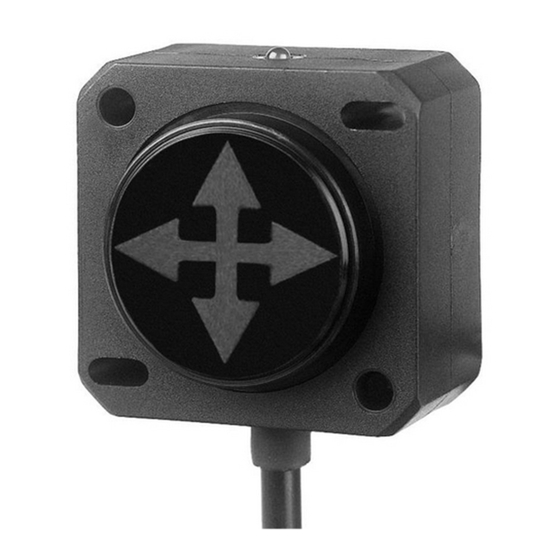
DIS Sensors QG40N Benutzer- und Sicherheitshandbuch - Seite 3
Blättern Sie online oder laden Sie pdf Benutzer- und Sicherheitshandbuch für Zubehör DIS Sensors QG40N herunter. DIS Sensors QG40N 6 Seiten. Tilt/acceleration switch (sil1 plc)
Auch für DIS Sensors QG40N: Benutzerhandbuch (5 seiten), Benutzerhandbuch (15 seiten)

QG40N Tilt SIL1 PLc
User Safety Manual v1.3
The user of this safety device shall only use this device when:
•
he is educated to design in / use functional safety sensors.
•
he has taken knowledge of both the datasheet, the user manual and the Declaration of Conformity
•
the zeroing function and configuration with the QG40N configuration tool is only performed in the right position by
an authorized person. Manufacturer is not responsible for any damage caused by these customer-setting, even when
the manufacturer defaults are used.
•
the bandwidth settings (filtering) are set according to the application demand
•
the device is used inside the specified environmental situation
The user of this safety device shall consider its output as 'unsafe' in the following situations:
•
the device output used is non-conducting (non-conducting should lead to 'low' thanks to external pull down resistor)
If two outputs are used, the device shall be considered as 'unsafe' even if only one output is non conducting.
Safety level
4
SIL safety level: SIL CL1 (claim limit 1 according to IEC 62061)
PL safety level: PLc (according to EN ISO 13849)
Architecture: HFT=0 (according to IEC 62061) & CAT2 (according to EN ISO 13849)
This is a self-certified safety device
The firmware of this device is developed according to EN ISO 13849 and meets the SRESW requirements for both 'PL a to
d' and 'PL c or d'
See separate 'Declaration of Conformity' for all safety related parameters
Tilt switch sensor explained
5
An inclinometer measures the angle(s) of the device with respect to earth gravity, using earth gravity vector as external
reference. The inclinometer involved is based on an accelerometer. The acceleration values are used to calculate the angle(s).
The device takes both the static component (100%) and the dynamic component (partial, depending on frequency and
bandwidth-setting) into account.
The Tilt switch sensor realises the switching behaviour for the NPN/PNP outputs based on these inclinometer angles by the
internal microcontroller.
Acceleration switch sensor explained
6
An Acceleration sensor measures the acceleration in 1, 2 or 3 axes. Internally the sensor has a 'measuring interval'.
The sensor has two modes:
PEAK (default): The peak acceleration value is calculated over the fixed 40ms measuring interval.
RMS (optional): The RMS acceleration value is calculated over a factory programmable measuring interval of n*40ms,
where n=integer, with a max. of 10 seconds.
The acceleration switch sensor realises the switching behaviour for the NPN/PNP outputs based on these accelerations by the
internal microcontroller.
Safety function
7
The safety function of the Tilt switch sensor is to generate the requested switching behaviour based on acceleration values
(caused by gravitation) measured by a MEMS acceleration sensor chip. Based on this switching behaviour (one non-
conducting output = unsafe) the safety controller of the application can switch the machine to safe-mode in order to prevent
for a dangerous situation.
Example: a crane-arm having a maximum tilt angle w.r.t. the chassis. If the tilt angle of the crane-am exceeds a certain
critical value, it can become dangerous. To prevent for this a Tilt switch can be mounted on the crane arm, measuring angle
of the crane arm. The safety controller of the application should monitor the Tilt switch outputs and should switch the crane
to safe-mode as soon as one of the Tilt switch outputs become non-conducting. This will significantly reduce the risk of a
dangerous situation to happen.
page 3 of 6
3
