Introduction
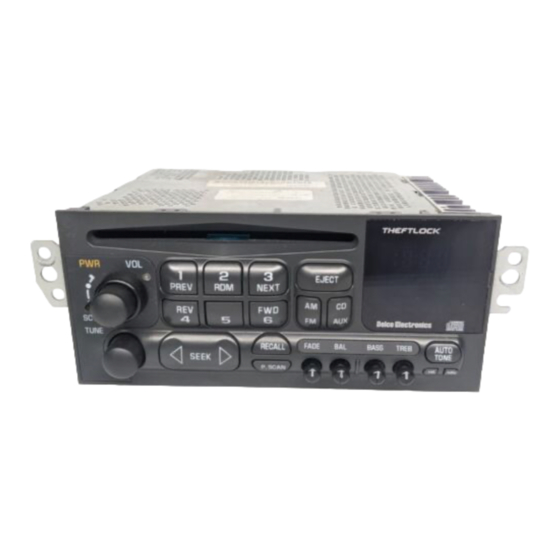
The BLU-C5 module, adds music streaming capabilities to all C5 with original CD
or Cassette radio (Bose o non-Bose). User elect to install module behind the
radio or (if available) to 10-pin plug in trunk/hatch. If vehicle has optional 12-disc
changer; it must be disconnected. To retain 12-disc changer purchase our
A2D-C5
instead. Once installed, pair smartphone, tablet etc. and stream Apple
music, navigation, Spotify, XM radio, Pandora, audio books and other application
while on the road to work or cruising around town.
Note: The BLU-C5 does not interfere with existing radio operation; however,
optional 12-disc changer (if present); must be disconnected.
For more, go to frequently asked question at the end of this guide.
Installation 1: (
To radio with PXHGM4 harness
Using the PXHGM4 harness, users connect module behind radio
cavity. 12-disc changer (if present) must be disconnected at
changer location. With the PXHGM2 harness, users connect
module to 10-pin plug in trunk/hatch and should proceed to
installation 2 on page 4.
Click links below for radio removal video)
Radio removal required. (
https://www.youtube.com/watch?v=Gcrlufo1ctc
https://www.youtube.com/watch?v=WTbWYNJTSDs
1.
Press black release tab to disconnect factory 20-pin plug (See Fig. 1)
C5 radio connector
)
Fig. 1
2. Connect factory 20-pin plug removed from radio to matting connector
on installation harness (See Fig. 2).
Fig. 2
PXHGM4 installation harness
3. Connect installation harness 20-pin black/gray (See Fig. 2) to radio
20-pin connector vacated in step 1
4. Ensure module dip-switches #3 and #8 are "ON" or down (See Fig. 3)
Fig. 3
5. Connect installation harness 22-pin Molex plug (See Fig. 2) to module
22-pin Molex connector (See Fig. 4)
Fig. 4

