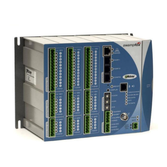
Abbey swampfox SF1 Installationshandbuch - Seite 3
Blättern Sie online oder laden Sie pdf Installationshandbuch für Controller Abbey swampfox SF1 herunter. Abbey swampfox SF1 8 Seiten. Pump station controller

Digital Inputs
General Description
Positive voltage-activated
DRY
CONTACTS
(EG. RELAY
CONTACTS
SWITCHES)
FIELD
SUPPLY
Digital Inputs – Externally Powered
By default Digital Inputs 0..3(, 12..15, 24..27 for SF3) are assigned to Pulse Counts
or Rates 0..3(, 4..11 for SF3). If Microlink-compatible pulse input mapping is
configured in Powerlink then Digital Inputs 9..6(, 21..18, 33..30) are mapped to
Pulses or Rates 0..3(, 4..11).
DRY
CONTACTS
(EG. RELAY
CONTACTS
SWITCHES)
Digital Inputs – Internal Pullup
Analog Inputs
General Description
Positive 4~20mA current
4~20 mA
TRANSDUCERS
100 mA
MAX
Analog Inputs – Internally Powered
IG-619-2.2-2015-Mar
Inactive, LED off
0~+1.8V
D.INs
+ 12V
11
10
1
0
GND
For RTUs with a –d suffix, the Digital Inputs are
D.INs
internally pulled up to the 12V rail.
The are activated by pulling the input to
1
a switch or relay contact.
0
GND
Inactive, LED off
0~+4mA
A.INs
+ 24V
3
2
1
0
GND
Active, LED on
+4.5~36.0V
200 mA
MAX
DRY
CONTACTS
(EG. RELAY
CONTACTS
SWITCHES)
Digital Inputs – Internally Powered
Active, LED on
Maximum
+4~20mA
±5V ±40mA
4~20 mA
TRANSDUCERS
FIELD
SUPPLY
Analog Inputs – Externally Powered
2
Maximum
Resistance
±60V DC
12kΩ to GND
D.INs
+ 12V
GND
GND
Resistance
120Ω to GND
A.INs
+ 24V
GND
Installation Guide
11
10
1
0
via
3
2
1
0
