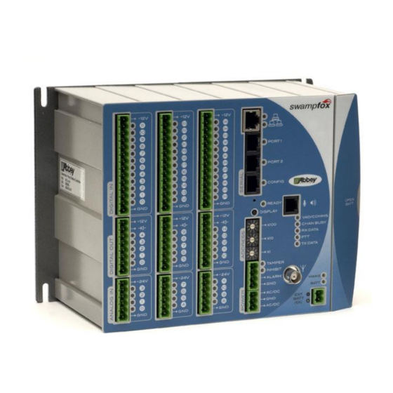
Abbey swampfox SF1 Installationshandbuch - Seite 7
Blättern Sie online oder laden Sie pdf Installationshandbuch für Controller Abbey swampfox SF1 herunter. Abbey swampfox SF1 8 Seiten. Pump station controller

Mains and Battery LEDs
's internal battery charger charges the internal battery, or an external
The
swampfox
12V sealed lead acid battery (6Ah or more) connected to the
connector. While power is present, the
state:
Mains LED
Battery LED
Green
Green
Red
Green
Either
Red
Unlit
Green
Green
Green flashing
Green
Red flashing
Other Front Panel Items
The
LED illuminates red when
COMMS
master.
The
button turns the front panel indicators on and off. The ready LED is
DISPLAY
always enabled.
The
ADDRESS SWITCHES
swampfox only examines the address
switches when it starts up or is reset
All
pins, the
GND
all connected inside the
IG-619-2.2-2015-Mar
swampfox power, charger and battery status
Normal
Backup
Battery Low
12V Powered
Charging
Charge Failure
set
swampfox
connector negative pin, and the antenna shield, are
EXT BATT/DC
.
swampfox
and
MAINS
BATT
POWER energized, battery OK, not charging
POWER not energized, running from battery
Battery voltage low (or battery disconnected)
Powered through EXT BATT/DC
Mains failed while charging, or faulty battery
cannot communicate with a
swampfox
's three digit RTU address.
6
EXT BATT/DC
indicators show
swampfox
Installation Guide
's
