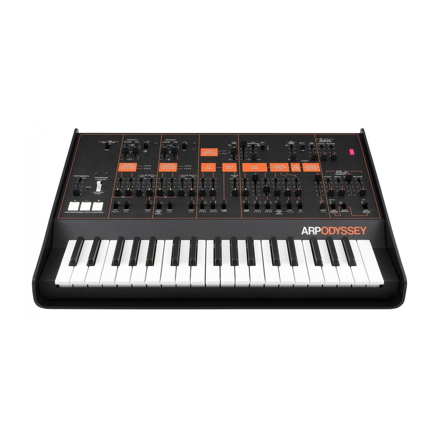
ARP ODYSSEY Handbuch - Seite 8
Blättern Sie online oder laden Sie pdf Handbuch für Synthesizer ARP ODYSSEY herunter. ARP ODYSSEY 18 Seiten. Electronic music synthesizer
Auch für ARP ODYSSEY: Benutzerhandbuch (18 seiten)

9.
The
two
envelope generators
are controllers.
They
are most often used
to
program
the
attack and
decay
of events
by
controlling
the
gain of
the
VCA or the
frequency
of
the
VCF.
The
upper envelope generator
in Figure O has
two control sliders, one for
attack time,
and
one for
release time.
It
is referred to as
the
AR generator. The lower
generator
has
con-
trols for
attack time, decay time, sustain level,
and
release time,
and
is thus
abbreviated as the
ADSR generator.
With your Odyssey controls set as
in Figure B,
feed pink noise into the audio mixer and close
the VCA gain slider all
the
way
down.
Open
the
control attenuator under the VCA all the
way as in Figure
P, and depress any key on
the keyboard. Raise the attack slider on
the
AR generator a little way and
depress
a key
again. Continue
to do
this, each time
raising
the attack control a little more until
it is
all
the way up.
Then
move it down again and
repeat
the whole procedure using the release
slider.
Now experiment with VCA control by the
ADSR generator; move the selector switch un-
der the VCA control attenuator down as in
Page 12 ARP ODYSSEY
Envelope generators
Figure
P
and
try
various settings
of the four
ADS
R
controls.
By closing the
VCF freq
slider
and opening the
third attenuator
under the VCF
all
the way as
in
Figure Q, you can give yourself
a
similar
introduction to
ADSR and
AR control of the
VCF.
Experiment too with various
combina-
tions of
the
VCF
freq
and control attenuator
settings, and with various
mixes {by means
of
the input
attenuators
to the
audio
mixer)
of
J: ~ ; : ~ ~"LED
signals
from
VCO
1
and
VCO
2.
·l::'.:
r--;,;v:~:E ~T;;;--,
Up to now you have been triggering
the
enve-
4
a
•1c•
OE
.
CAY
SUSTA
.
IN
RELEASE
lope generators only from the keyboard.
By
_
-1-1-1
means of the three switches at the
bottom right
of
Figure
R, you can also
trigger the
er'lve.lope
generators with
the LFO.
Move all three
switches down and set the other controls of
J_
your
Odyssey
for AR or ADSR control of the
., ~/
08
".:;-i
J
l
1
. ~ :07
VCF or VCA as in Figure R; now try
different
8 !
"g
9
settings of the LFO freq slider from low to
AOSR
l f l i
.•uro
REPEAT
.r-.._
REPEAT
REPEAT
JU1
high. With the first switch down and the sec-
..,_ ___
.n.n._
_ _ _ _ _ . . . . . _
_ .
ond switch up, a series of events will be pro-
duced (triggered) by the
LFO,
but only when
a key is depressed.
This
is useful
in
simulating
---banjo-picking
and strumming as in Patch
11.
Return switches under ADSR and AR to upper
position.
Figure P
VOLTAGE
CONTROLLED
ll
l_ l_ l_
ICYBO
5m
ADSR
CV
.I'--,__
8 B
l!!I
S/H
LFO
AR
MIXER
fV'v
r-\_
PtD~L
Figure
Q
Figure
R
Figure
S
10.
The low frequency oscillator (LFO) is
a
controller;
its
output signal
is never
used as
raw
material but only to control other
functions within the
Odyssey.
You have
al-
ready heard it control VCO
1
in
Figure
E ;
now, by
following
the
settings of Figure S,
listen
alternately
to LFO square wave
control
of VCO 1
and
LFO sine wave
control.
In
one
case
you
hear a
vibrato,
in the
other a trill.
Experiment with
various settings of
the LFO
freq slider and of the control
attenuator
under VCO
1.
The L FO can also be used to
govern
the
oper-
ation
of the sample/hold
circuit and
the
envelope generators
which
you
will read
about
later.
11. The sample and hold mixer (S/H mixer)
selects and
combines signals
to
be
fed
to the
sample and
hold circuit. These
signals can also
be
routed
to
control
VCO
2 and
the
VCF.
Under
each of these
two
functions
is
a switch
labeled"S/H
mixer or pedal.,,
When the
foot
pedal
is
plugged
into
the
Odyssey, the
lower
position
of these switches selects control by
the pedal;
if the
foot pedal
is disconnected
Low frequency oscillator
ARP
ODYSSEY
Pag_e
13
