Alto ? MICtube Benutzerhandbuch - Seite 4
Blättern Sie online oder laden Sie pdf Benutzerhandbuch für Verstärken Alto ? MICtube herunter. Alto ? MICtube 12 Seiten. Stereo tube preamp
Auch für Alto ? MICtube: Benutzerhandbuch (15 seiten), Benutzerhandbuch (16 seiten)

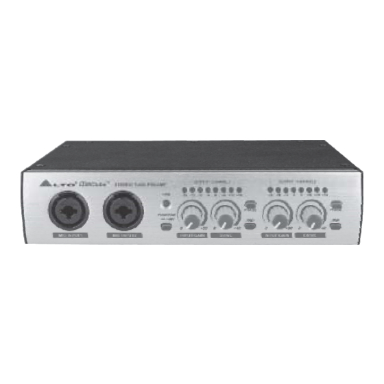
Front Panel:
1 Power LED
It will light-up when the unit is connected to an AC outlet.
2 Output Level Display LEDs (CHANNEL 1 & 2)
It informs you about the output gain of Channel 1 & 2. For optimal operation you
should visualize the signal from -2 dB to 0 dB. If you operate at a low output
level (-24 dB), you will experience a high noise level while operating at levels higher
than +6 dB. It will saturate the output stage and produce unwanted distortion.
3 Phantom Power Switch
This switch activates the +48 volts phantom
power to supply condenser microphones and/or
any other device requiring phantom power. The
+48V is applied both to the positive (pin2) and
negative inputs (pin3) of the XLR connector:
Caution:
Please make sure that you are using an appropriate condenser
microphone before you activate this switch to supply the +48V phantom power.
Read the microphone operating instructions. Some condenser microphones
might need another type of power supply and old ribbon microphones maybe be
damaged by the +48V voltage.
4 Phase Reverse Switch
These two switches will reverse the audio signal's phase by 180 . Under normal
operation, there is no need to use these switches. However, in some cases, it
might be necessary, for example: the inversion of the pins of the XLR connector
may be necessary to alter the audio phase of two link microphones to compensate
for phase cancellation. It may be required that the wiring of a cable's XLR connector
be switched to successfully utilize Phantom power.
LTO
MIC INPUT1
6
2
3. CONTROL ELEMENTS
R
MICtube
TM
STEREO TUBE PREAMP
PHANTOM
MIC INPUT2
6
1
2
OUTPUT / CHANNEL1
PWR
24
18
12
6
0
6
12
18
15
6
8
3
12
18
11
1
6
21
PHASE
15
1
2
GAIN
26
48V
1
36
28
4
0dB
+45dB
+5dB
norm
INPUT GAIN
DRIVE
8
3
7
XLR Connector
PIN (Ground)
PIN (Positive)
PIN (Negative)
4
2
OUTPUT / CHANNEL2
24
18
12
6
0
6
12
18
15
6
8
3
12
18
11
1
6
21
PHASE
15
1
2
GAIN
26
20dB
1
36
28
4
0dB
+45dB
+5dB
norm
INPUT GAIN
DRIVE
5
7
8
Phantom
Power Supply
GND
+48V
+48V
4
20dB
5
