Balmar MAX CHARGE MC-614 Installations- und Betriebshandbuch - Seite 2
Blättern Sie online oder laden Sie pdf Installations- und Betriebshandbuch für Controller Balmar MAX CHARGE MC-614 herunter. Balmar MAX CHARGE MC-614 9 Seiten. Multi-stage voltage regulator
Auch für Balmar MAX CHARGE MC-614: Installations- und Betriebshandbuch (20 seiten), Installations- und Betriebshandbuch (20 seiten), Schnellstart-Handbuch (2 seiten)
CAUTION: The following instructions are intended for use by experienced marine
electrical installers. If you are not experienced at installing electrical system
components, we recommend the use of a qualified marine electrical technician.
Regulator Installation
The following information is intended to provide the installer with the
basic information required to complete installation. This section of the
installation manual will deal with mounting, wiring connections and ba-
sic programming for battery type. Additional information regarding ad-
vanced programming adjustments and troubleshooting are addressed
later in the manual.
Unpacking The Box
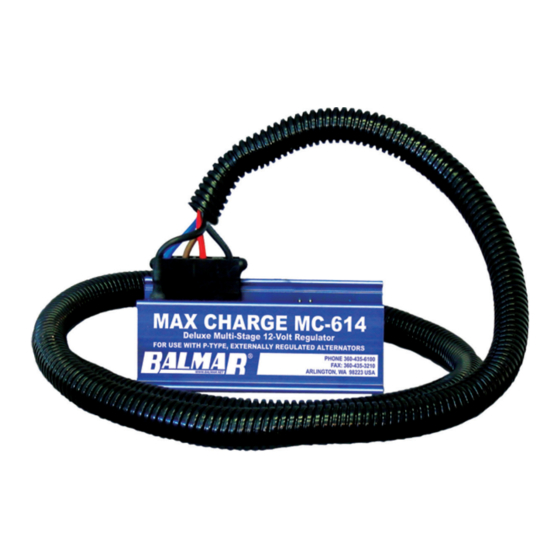
Your Max Charge MC-614-H regulator kit is packaged with the
following items:
•
Max Charge MC-614 regulator
•
54" wiring harness
•
Fused (1A) battery sense wire pigtail
•
Magnetic programming tool
•
Installation and operation manual
If any of the listed items is not included with your regulator kit, call our
customer service department at 360-435-6100. Please note -- if your regulator box is marked Max Charge MC-614, with-
out the "H" designation, your kit will not include the wiring harness or fused battery sense pigtail.
Locate And Mount The Regulator
Choosing a mounting location for your voltage regulator should be deter-
mined based on the following factors; distance from alternator, distance from
inverters, transmitters and other sources of RF noise, convenient access
and readability of the display. The regulator wiring harness is 54 inches long,
providing a three to four foot radius for mounting. Ample airflow is essential
for the regulator's proper operation. Ensure that the regulator is free from
obstructions that restrict air movement around or below the regulator's alu-
minum heat sink. While the regulator is designed to operate safely in condi-
tions typical of a marine engine compartment, the regulator may be better
protected, and easier to use and monitor if mounted outside of the engine
compartment.
Should it be necessary to install the regulator further than 54 inches from
the alternator, ensure that any wire extensions are properly connected, as
resistance in the harness wiring can affect charging efficiency. If harness
length must reach beyond approximately eight feet, replace the RED power
and BLUE field wires with larger gauge wire that's sized to ensure voltage
drop < 3%.
Basic Wiring Installation
The regulator's wiring harness includes six wires required for standard
installation. Four of those wires are connected to the regulator via a
Ford-style plug connector that's pre-installed on the regulator. These
wires include the Ground (BLACK), Power (RED), Ignition (BROWN)
and Field (BLUE). Plug is shown at right.
In addition, the harness includes a separate Stator (WHITE) wire. The
proper terminal connection points for this, and additional wiring connec-
tions, are illustrated on the pin location legend shown and discussed on
the following pages.
- 2 -
If there is little or no magnetic pull at the pulley shaft or at the rear bearing, initiate the following test:
With the key off and the engine off, remove the large harness plug from the regulator.
1.
Insert the end of a short length of electrical wire to the RED connector slot of
the regulator harness and the other end of the wire to the BLUE connector slot.
This bypasses the regulator and tests the alternator and the harness.
2.
Using your steel screwdriver, inspect for a magnetic field as described above.
3.
With your voltmeter, check for voltage on the blue wire at the alternator. If volt-
age does not exist, the harness may be at fault. If voltage does exist at the
harness, but no magnetism is present, the alternator is likely to be malfunction-
ing.
4.
If a magnetic field is present. Both harness and alternator brushes and rotor
appear to be working properly. If no magnetic field is present, proceed with the
next test.
Testing the actual output of the alternator is known as "Full Field Testing". This can
be accomplished by jumping a positive 12VDC current to the field terminal at the
rear of the alternator. This test eliminates both the regulator and the harness, mak-
ing it easier to isolate your investigation to the alternator.
CAUTION: Ensure that all voltage sensitive equipment is turned off prior to starting the engine. Voltage is unregulated
during this test and could damage sensitive electronics. DO NOT let the engine run any longer than necessary to detect
charging. If the system is not charging, remove the alternator and have it inspected by a qualified alternator shop, or call
Balmar for warranty evaluation.
To test the alternator:
1.
Clip a jumper wire to the positive post of the alternator, or on the battery side of the isolator (if an isolator is in use).
Use a SHIELDED alligator clip for post attachment. Unintentional contact between the alligator clip and the alternator
case could result in damage to your electrical system.
2.
Disconnect the field wire from the rear of the alternator and attach the other end of the jumper wire to the alternator's
Field terminal (F). CAUTION: Do not allow the wire to contact the case while it is attached to the positive post. The
case is grounded and severe damage could occur.
3.
The regulator is now bypassed. When the ignition is engaged and the motor is started, the voltage should rise and
charging current should be present.
4.
The motor should be run long enough to determine that charging voltage is present. Unregulated voltage can rise
quickly. Do not allow extended unregulated charging to occur without carefully monitoring voltage levels. If the alterna-
tor fails to generate voltage during field testing, a malfunction of the alternator is likely. Contact your local alternator
repair shop or Balmar's technical service staff for recommendations.
Conclusion
If your readings differ substantially from the "Expected Readings" listed in the troubleshooting charts, the regulator may
be malfunctioning, or there may be a continuity problem. Contact our technical support staff at (360) 435-6100. If you
determine that repair service is necessary for either your alternator or regulator, please gather the following information
before contacting our service technicians: Make and model of alternator. Model of voltage regulator and date of mfg. (date
punched on rear side label of regulator). Voltage readings on red, brown and blue wire at regulator with engine off, key on.
Voltage readings on red, brown and blue wire at regulator with engine running at a fast ideal 1400 rpm.
NOTES:
- 15 -