CAMERA LINK PHRONTIER PHIRE PHR-85-M025 Benutzerhandbuch - Seite 5
Blättern Sie online oder laden Sie pdf Benutzerhandbuch für Adapter CAMERA LINK PHRONTIER PHIRE PHR-85-M025 herunter. CAMERA LINK PHRONTIER PHIRE PHR-85-M025 13 Seiten. Fiber adapters

STEP
1
Power off camera and frame grabber
2
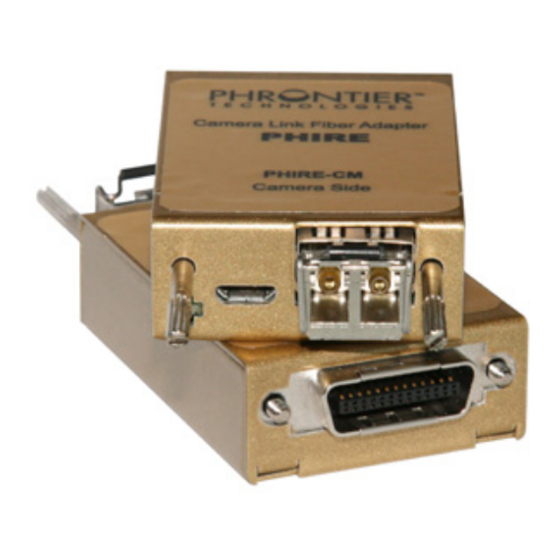
Plug PHIRE-CM module to the camera and secure the module with thumb screws
3
Plug PHIRE-FG module to the frame grabber and secure the module with thumb
screws
4
Take off the caps on LC connectors at both ends of optical fiber cable.
Take off the caps on the LC fiber ports of PHIRE-CM and PHIRE-FG.
Plug LC fiber cable to both PHIRE-CM and PHIRE-FG. Users should hear a click
sound, which indicates a successful mate.
5
Connect power plugs to PHIRE-CM and PHIRE-FG. Users should hear a click
sound, which indicates a successful mate.
STEP
6
Power up Camera
7
Power up the equipment (e.g., PC) where the frame grabber is installed
8
Power up PHIRE-FG by plugging AC/DC adapter into the AC power source
9
Power up PHIRE-CM by plugging AC/DC adapter into the AC power source
Table 1 Installation and Power up Steps for the PHIRE System
5. Functionality
The PHIRE™ system consists of two adapter modules, PHIRE-CM on the camera side and
PHIRE-FG on the frame grabber (or PC) side. The block diagram of the PHIRE system is shown
in Figure 1. All electrical signals on the left-hand side of PHIRE-CM have a one-to-one
correspondence with the ones on the right-hand side of PHIRE-FG. Each adapter module
converts its input electrical signals into a single optical signal and sends it to the other adapter
module. It also receives a single optical signal from the other adapter module and converts it
back into multiple output electrical signals. With the PHIRE™ system, the signal transmission
distance between the camera and the frame grabber can be extended up to 80 kilometers
without any repeaters or amplifiers in between. Most importantly, the PHIRE™ system is totally
transparent to the camera and the frame grabber, which means seamless and easy system
integration. The functionality of the PHIRE system is described in details below.
FVAL/LVAL/DVAL/SP
IMAGE DATA (24b)
PIXEL CLOCK
CC1 – CC4
SERIAL PORT
D-A-CH
FrAnCe – Telecom
Phrontier Technologies
Laser 2000 GmbH
Laser 2000 SAS
82234 Wessling
78860 St-N. l. Bretèche
Tel. +49 8153 405-0
Tel. +33 1 30 80 00 60
www.laser2000.de
www.laser2000.fr
INSTALLATION STEPS
POWER UP STEPS
PHIRE-CM
TM
Figure 1 PHIRE
System Diagram
FrAnCe – Photonic
PHIRE User Manual V4
Laser 2000 SAS
33600 Pessac
Tel. +33 5 57 10 92 80
www.laser2000.fr
PHIRE-FG
FVAL/LVAL/DVAL/SP
IMAGE DATA (24b)
PIXEL CLOCK
CC1 – CC4
SERIAL PORT
IberIA
Laser 2000 SAS
28034 Madrid
Tel. +34 617 308 236
www.laser2000.es
5
norDICs
Laser 2000 GmbH
112 51 Stockholm
Tel. +46 8 555 36 235
www.laser2000.se
