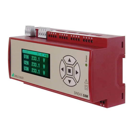
Camille Bauer SINEAX CAM Betriebsanleitung - Seite 5
Blättern Sie online oder laden Sie pdf Betriebsanleitung für Messgeräte Camille Bauer SINEAX CAM herunter. Camille Bauer SINEAX CAM 12 Seiten. Graphic display for sineax cam
Auch für Camille Bauer SINEAX CAM: Betriebsanleitung (19 seiten)

Network /
application
2
5
8
Three-wire
L1
three-phase
L2
system
L3
asymmetri-
cal load
2
5
8
Aron
measuring
u
v
u
v
circuit
U
V
U
V
L1
L2
L3
2
5
L1
L2
L3
N
2
5
Four-wire
L1
three-phase
L2
system
L3
asymmetri-
N
cal load
2
5
u
u
x
x
X
X
U
U
L1
L2
L3
N
3 single-pole isolated voltage transformers
in the high-voltage system
Example with ACP FLEX 300x_5 current sensors 30/300/3000A, which need a 3V power supply
Terminal arrangement
3
9
1
7
2
5
8
1
k
L1
K
L2
L3
8
2
5
1
1
3
7
9
u
u
u
x
x
x
X
X
X
k
k
l
U
U
U
L1
K
K
L
k
l
L2
L3
K
L
8
11 1
4
6
9 10 12
3
7
1
4
6
9 10 12
8
11
3
7
k
l
k
l
K
L
k
l
K
L
k
l
K
L
K
L
8
11
1
3
4
6
7
9 10 12
u
x
X
k
l
k
l
U
K
L
k
l
K
L
k
l
K
L
K
L
U1
U2
U3
N
2
5
8
11
L1
L2
L3
N
Network /
application
3
7
9
l
L
k
l
K
L
3
9
7
Four-wire
l
three-phase
L
k
l
system
K
L
asymmetri-
cal load
Open Y
circuit
Split phase
("Two-phase
network")
asymmetri-
cal load
I1
I2
I3 COM
+ 3V -
1
3
4
6
7
9
Terminal arrangement
2
8
11 1
3
4
6
7
9 10 12
L1
L2
L3
N
2
8
11
1
3
4
6
7
9 10 12
k
l
k
l
L1
K
L
k
l
L2
K
L
L3
K
L
N
K
1
2
3
4
5
6
7
8
u
u
x
x
k
k
k
l
X
X
l
U
U
L1
K
L
L
L2
K
L
L3
K
N
2 single-pole isolated voltage transformers
in the high-voltage system
2
5
1
3 4
L1
L2
N
2
1
3
4
5
k
l
k
L1
K
L
L2
K
N
IN COM
10
12
k
l
L
9 10
11 12
k
l
l
L
K
L
6
11
6
10 12
11
l
k
l
L
K
L
5
