esera automation 1-Wire Hub III DC Benutzerhandbuch - Seite 3
Blättern Sie online oder laden Sie pdf Benutzerhandbuch für Kontrolleinheit esera automation 1-Wire Hub III DC herunter. esera automation 1-Wire Hub III DC 6 Seiten. Auto-e-connect

Art. No. 11322
8
Software
Output voltage and current are measured by an integrated module. The module is addressed by a standard
command for the DS2450 module. Data output is provided either as Integer values (0 - 4095) or direct voltages,
depending on the used software product. Please refer to the following formulas depending on the data output:
Calculation with output of DS2450 values in Integer
DS2450, 5 V range, output Integer 0-4096 (12 Bit resolution)
voltage 5 V =
((5,0 / 4096) * 1.11) * DS2450_Port3
voltage 12 V = ((5,0/ 4096) * 2.63) * DS2450_Port1
(5,0 / 4096) * (DS2450_Port2 – 20) * 46
current 5 V =
(5,0 / 4096) * (DS2450_Port0 – 20) * 46
current 12 V =
Calculation with output of DS2450 analog values in mV
DS2450, 5 V range, 12 Bit resolution
voltage 5 V
= (DS2450_Port3 * 1.11) / 10
voltage 12 V
= (DS2450_Port1 * 2.63) / 10
current 5 V (mA)
= DS2450_Port2 / 20
current 12 V (mA) = DS2450_Port0 / 22
9
Connection plan
A connection plan and a connection example with further modules are available in our webshop.
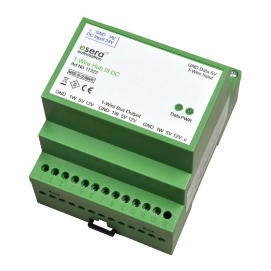
Pin assignment input, power supply, Bus Coupler/Controller
14 = plus supply voltage
15 = minus supply voltage
16 = grounding (PE)
23 = Ground 1-Wire input
24 = 1-Wire data line
25 = 5 V input from master (e.g. 1-Wire
Controller or 1-Wire Bus Coupler)
Pin assignment output, 1-Wire
network
1 = Ground / GND
2 = 1-Wire data line
3 = 5 V output maximum 0,5 A
4 = 12 V output maximum 1 A
5 = Ground / GND
6 = 1-Wire data line
7 = 5 V output maximum 0,5 A
8 = 12 V output maximum 1 A
9 = Ground / GND
10 = 1-Wire data line
11 = 5 V output maximum 0,5 A
12 = 12 V output maximum 1 A
13 = not connected
The "1-Wire Bus output 1" is specially designed to supply modules close to the 1-Wire Hub III. This output
is equipped with a cable length-compensation compared to cable lengths of the outputs 2 and 3.
Note:
5 V input voltage (terminal 25) is available at the output as "emergency power supply" even in case there is no 24
V power supply available at the output of the 1-Wire Hub.
Note: You can find the basics and tips for the 1-Wire Bus system in the ESERA Online Shop at
1-Wire basics or please refer to our eBook in the shop under Training/Documentation
All rights reserved. Reproduction as well as electronic duplication of this user guide, complete or in part, requires the written consent of
ESERA GmbH. Errors and technical modification subject to change. ESERA GmbH, ESERA-Automation 2020
www.esera.de
11322 V2.0 R1.1 Manual
Page 3 of 6
