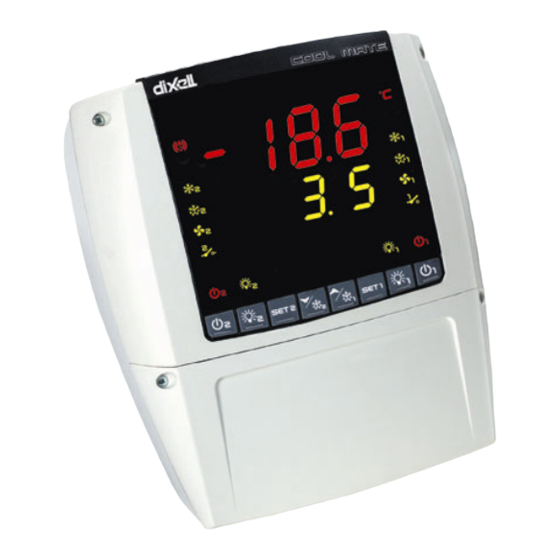
dixell COOL MATE XLR470 Betriebshandbuch - Seite 10
Blättern Sie online oder laden Sie pdf Betriebshandbuch für Temperaturregler dixell COOL MATE XLR470 herunter. dixell COOL MATE XLR470 18 Seiten. Dual temperature controller

dIXEL
dIXEL
dIXEL
dIXEL
OP : the digital input is activated by opening the contact.
i2F
Digital input 2 operating mode(2-3): configure the digital input function:
MP1 = door switch 1; MP2 = door switch 2, MP: door switch (it's used by both the sections); EA1 = generic alarm section 1; EA2 = generic
alarm section 2; EAL = generic alarm (it's used by both the sections); bA1 = serious alarm mode section 1; bA2 = serious alarm mode
section 2; , bAL = serious alarm mode section (it's used by both the sections); dF1 = Start defrost, section 1; dF2 = Start defrost, section 2;
dEF = Start defrost (it's used by both the sections); oF1 = remote on/ off, section1; oF2 = remote on/ off, section 2; oFF = = remote on/ off
(it's used by both the sections); ES = Energy Saving
odc1
Compressor and fan status when open door, section 1: no = normal; Fan = Fan OFF; CPr = Compressor OFF; F_C = Compressor and
fan OFF;
rrd1= Outputs restart after door open alarm, section 1: n = status of outputs according to odc1; Y= outputs restart working.
did1
Time interval delay for digital input alarm, section 1:(0
defines the time delay between the detection and the successive signalling of the alarm.
Compressor status when open door, section 2: no ,Fan = normal; CPr, F_C = Compressor OFF.
odc2
rrd2
Outputs restart after door open alarm, section 2: n = status of outputs according to odc2; Y= outputs restart working.
did2
Time interval delay for digital input alarm, section 2:(0
defines the time delay between the detection and the successive signalling of the alarm.
OTHER
oA6
Auxiliary output configuration (29-30-31): (cP1 / cP2 / dF1 / dF2 / Fn1 / Fn2 / Lg1 / Lg2 / on1 / on2 / db1 / db2 / ALr) cP1= compressor
1, cP2= compressor 2; dF1= defrost 1; dF2= defrost 2; Fn1= fans 1; Fn2= fans 2; Lg1= light 1; Lg2= light 2; on1= On/Off; on2= On/Off;
db1= n.u.; db2= n.u.; ALr= alarm.
tbA
Alarm relay silencing: y= relay silencing with alarm; n= silencing only alarm signals
AoP
Alarm relay polarity: cL= active closed; oP= active opened
HES1 Temperature increase during the Energy Saving cycle, section 1: (-30÷30°C / -54÷54°F) sets the increasing value of the set point1
during the Energy Saving cycle.
HES2 Temperature increase during the Energy Saving cycle, section 2: (-30÷30°C / -54÷54°F) sets the increasing value of the set point2
during the Energy Saving cycle.
TO SET CURRENT TIME AND WEEKLY HOLIDAYS (ONLY WITH RTC)
Hur
Current hour (0 ÷ 23 h)
Min
Current minute (0 ÷ 59min)
dAY
Current day (Sun ÷ SAt)
Hd1
First weekly holiday (Sun ÷ nu) Set the first day of the week which follows the holiday times.
Hd2
Second weekly holiday (Sun ÷ nu) Set the second day of the week which follows the holiday times.
Hd3
Third weekly holiday (Sun ÷ nu) Set the third day of the week which follows the holiday times.
N.B.
Hd1,Hd2,Hd3 can be set also as "nu" value (Not Used).
TO SET ENERGY SAVING TIMES (ONLY WITH RTC)
ILE
Energy Saving cycle start during workdays: (0 ÷ 23h 50 min.) During the Energy Saving cycle the set point is increased by the value in
HES so that the operation set point is SET + HES.
Energy Saving cycle length during workdays: (0 ÷ 24h 00 min.) Sets the duration of the Energy Saving cycle on workdays.
dLE
ISE
Energy Saving cycle start on holidays. (0 ÷ 23h 50 min.)
dSE
Energy Saving cycle length on holidays (0 ÷ 24h 00 min.)
TO SET DEFROST TIMES (ONLY WITH RTC)
L1d1÷L1d6 Workday defrost start SECTION 1 (0 ÷ 23h 50 min.) These parameters set the beginning of the eight programmable defrost cycles
during workdays. Ex. When L1d2 = 12.4 the second defrost starts at 12.40 during workdays.
S1d1÷S1d6 Holiday defrost start (0 ÷ 23h 50 min.) These parameters set the beginning of the eight programmable defrost cycles on holidays.
Ex. When S1d2 = 3.4 the second defrost starts at 3.40 on holidays.
L2d1÷L2d6 Workday defrost start SECTION 2 (0 ÷ 23h 50 min.) These parameters set the beginning of the eight programmable defrost cycles
during workdays. Ex. When L2d2 = 12.4 the second defrost starts at 12.40 during workdays.
S2d1÷S2d6 Holiday defrost start (0 ÷ 23h 50 min.) These parameters set the beginning of the eight programmable defrost cycles on holidays.
Ex. When S2d2 = 3.4 the second defrost starts at 3.40 on holidays.
N.B. : To disable a defrost cycle set it to "nu"(not used). Ex. If L1d6=nu ; the sixth defrost cycle is disabled
UTILITY
Adr1
RS485 serial address, section 1 (1÷247): Identifies section 1 address when connected to a ModBUS compatible monitoring system.
Adr2
RS485 serial address, section 2 (1÷247): Identifies section 2 address when connected to a ModBUS compatible monitoring system.
If Adr1 = Adr2
dP1
First probe display
dP2
Second probe display
dP3
Third probe display
dP4
Fourth probe display
rEL
Release software: (read only) Software version of the microprocessor.
Parameter table: (read only) it shows the original code of the dIXEL parameter map.
Ptb
Pr2
Access to the protected parameter list (read only).
1592017050 XLR470 GB r1.0 24.05.07.doc
Operating manual
255 min.) With i1F or i2F = EAL1 or bAL1 (external alarms), "did" parameter
÷
255 min.) With i1F or i2F = EAL1 or bAL1 (external alarms), "did" parameter
÷
XLR470
cod. 1592017
cod. 1592
cod. 1592
cod. 1592
017050
017
017
050
050
050
10/18
