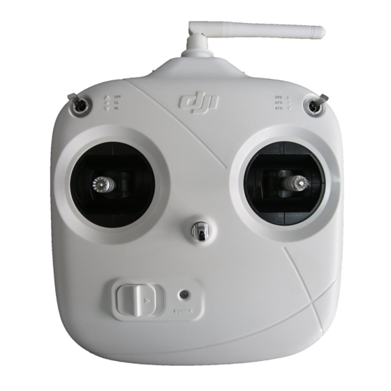
dji DT7 Benutzerhandbuch - Seite 4
Blättern Sie online oder laden Sie pdf Benutzerhandbuch für Fernsteuerung dji DT7 herunter. dji DT7 5 Seiten. 2.4g rc system
Auch für dji DT7: Benutzerhandbuch (7 seiten)

Master and slave remote controllers connection diagram:
Recommended Mapping for DJI DT7 RC with A2 and DJI Gimbal
Controller Unit Channel
A
E
T
R
U
Gear
ROLL
PAN
TILT
MODE
Photo
Video
Note that these settings should be configured according to your requirements.
Follow the steps below to check if the channels are working properly:
1. Run the A2 Assistant and go to the Channel Mapping page.
2. Move the Master remote controller's sticks and switches to ensure they are working
properly on the Channel Mapping page.
DT7 Power LED Indicator
Power LED Indicator Sound
Solid
—
Quickly
Slowly
• Turn on the remote controller before powering on the aircraft. Power off the aircraft
before turning off the remote controller.
• Avoid interference between the remote controller and other wireless equipment.
• Store the remote controller in a cool, dry place away from direct sunlight to
ensure the built-in LiPo battery does not overheat.
• Make sure that the remote controller is fully charged before use.
• The remote controller will power off automatically when the battery voltage
drops below 3.3 V. Land and charge the battery as soon as possible when the
low voltage alert occurs to avoid loss of control during flight.
Using the DR16 Receiver
Connecting the DR16 Receiver to the Flight Control System
The DR16 Receiver is designed to be used with the below flight control system: NAZA-M
Lite,NAZA-M,NAZA-M V2,WooKong-M,A2. Connect the DR16 receiver to the correct
port (X2) on the main controller by using a 3-Pin cable. Then select the D-BUS receiver type
in the Assistant software.
Linking the DT7 & DR16
Linking Procedure
1. Power on the flight control system and the DR16 receiver.
2. Turn on the remote controller and place the remote controller 0.5 m - 1 m away from the
receiver.
3. Poke the link button on the receiver with a thin object and hold. Once the LED indicator on
the receiver blinks red, release it.
4. When the LED indicator becomes solid green, the link between the DT7 remote controller
and the DR16 receiver has been successfully established.
3
EN
Receiver Channel
A
E
T
R
U
X2
A
E
R
U
X1
X2
Remote Controller Status
None
Normal.
Low voltage (3.3-3.5 V). Charge the battery
B-B-B......
immediately.
An alarm will sound after 15 minutes of inactivity. It will
B--B--B......
stop once you start using the remote controller again.
Recommended Remote Controller Switch
Master remote controller J1
Master remote controller J2
Master remote controller J3
Master remote controller J4
Master remote controller S1
Master remote controller S2
Slave remote controller J1
Slave remote controller J2
Slave remote controller J4
Slave remote controller S1
Slave remote controller LD
Slave remote controller S2
