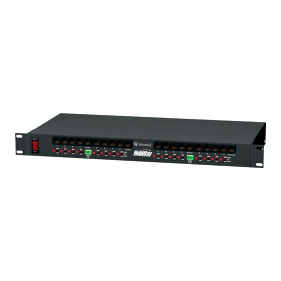
Altronix HubWay16Di Installationshandbuch - Seite 8
Blättern Sie online oder laden Sie pdf Installationshandbuch für Schalter Altronix HubWay16Di herunter. Altronix HubWay16Di 9 Seiten. Passive utp transceiver hub with integral isolated camera power

Rack Mount Installation
1- Remove and discard factory installed screws from both sides of rack chassis (Fig. 6a).
2- Install mounting brackets (A) on the left and right side of rack chassis using the
four (4) flat head screws (B) (included) (Fig. 6b).
3- Place unit into desired EIA 19" rack position and secure with mounting screws (not included) (Fig. 6c).
Fig. 6
Fig. 6a
Top
Remove
Wall Mount Installation
1- Install mounting brackets (A) on the left and right side of rack chassis using
four (4) flat head screws (B) (included) (Fig. 7a).
2- Place unit at desired location and secure with mounting screws
(not included) (Fig. 7b).
Caution: It is necessary to
make sure mounting screws
are securely fastened to a
beam when installing the
unit vertically.
Shelf Installation
1- Position and affix rubber pads (C) (included) at each
corner on the bottom of the unit (Fig. 8).
2- Place unit in desired location.
Fig. 8
Altronix is not responsible for any typographical errors.
140 58th Street, Brooklyn, New York 11220 USA, 718-567-8181, fax: 718-567-9056
website: www.altronix.com, e-mail: [email protected], Lifetime Warranty, Made in U.S.A.
IIHubWay8Di/HubWay16Di
- 8 -
Mounting Options:
Fig. 6b
Front
Left
Fig. 7
Fig. 7a
B
Left Side
C
Rubber Pad
Top
Front
Left
B
Fig. 7b
A
J15N
Fig. 6c
A
Dotted lines indicate studs
behind sheetrock.
Mounting Hardware
Two (2) mounting brackets
A
Six (6) flat head screws
B
for mounting brackets.
Four (4) rubber pads.
C
Top
Front Left
(Included):
MEMBER
HubWay Passive Unit
