Altronix AL176UL Handbuch
Blättern Sie online oder laden Sie pdf Handbuch für Medienkonverter Altronix AL176UL herunter. Altronix AL176UL 4 Seiten. Access control power supply/charger
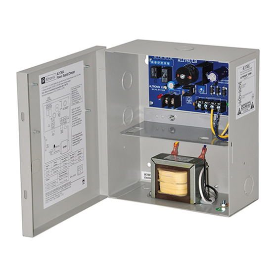
The AL176UL is a power-limited power supply/charger that converts a 115VAC / 60Hz input into 12VDC or 24VDC
output (see specifications). It is intended for use in applications requiring UL Listing for Access Control (UL294). It must
be installed in accordance with National and Local Electrical Codes and Regulations.
Agency Listings:
• UL Listed - U.S. and Canada for
Access Control Systems (UL294).
Input:
• Input 115VAC/60Hz, 0.6A.
Output:
• Field selectable 12VDC or 24VDC output.
• 1.75A supply current.
• Class 2 Rated power-limited output.
• PTC protected outputs, rated @ 2.5A.
• Filtered and electronically regulated output.
• Short circuit and thermal overload protection.
Output VDC
Jumper
12VDC
Jumper Removed
24VDC
Jumper On
Output
12VDC / 7 AH Battery
24VDC / 7 AH Battery
Wiring methods shall be in accordance with the National Electrical Code/NFPA 70/NFPA 72/ANSI, and with all local
codes and authorities having jurisdiction. Product is intended for indoor use only.
See Terminal Identification Chart on Pg. 2 for a description of each terminal function.
1. Mount unit in the desired location. Mark and predrill holes in the wall to line up with the top two keyholes in the
enclosure. Install two upper fasteners and screws in the wall with the screw heads protruding. Place the enclosure's
upper keyholes over the two upper screws; level and secure. Mark the position of the lower two holes. Remove the
enclosure. Drill the lower holes and install two fasteners. Place the enclosure's upper keyholes over the two upper
screws. Install the two lower screws and make sure to tighten all screws (Enclosure Dimensions, pg. 4).
2. Connect AC power to the black and white flying leads of the transformer. Secure green wire lead to earth ground.
Use 18 AWG or larger for all power connections (Battery, AC input). Use 22 AWG to 18 AWG for power-limited
circuits (DC output, AC FAIL and LOW BAT supervisory relays).
Keep power-limited wiring separate from non power-limited wiring (115VAC / 60Hz Input, Battery Wires).
Minimum 0.25" spacing must be provided.
CAUTION: Do not touch exposed metal parts. Shut branch circuit power before installing or servicing equipment.
There are no user serviceable parts inside. Refer installation and servicing to qualified service personnel.
3. Set the AL176UL to the desired DC output voltage by either removing/leaving jumper.
(see Power Supply Output Specifications).
Note: Measure output voltage before connecting devices. This helps avoiding potential damage.
AL176UL
AL176UL
Access Control Power Supply/Charger
Specifications:
Power Supply Output Specifications:
Max. Stand-by Load DC
1.75A
1.75A
Stand-by Specifications:
4 hr. of Stand-by and 5 Minutes of Alarm
Stand-by = 1.25A
Alarm = 1.25A
Installation Instructions:
Overview:
Battery Backup:
• Built-in charger for sealed lead acid or gel type batteries.
• Automatic switch over to stand-by battery
when AC fails.
• Maximum charge current 0.4A.
Supervision:
• AC fail supervision (form "C" contacts).
• Low battery supervision (form "C" contacts).
Visual Indicators:
• AC input and DC output LED indicators.
Enclosure Dimensions (H x W x D):
8.5" x 7.5" x 3.5" (215.9mm x 190.5mm x 88.9mm)
Max. Alarm Load DC
Battery (optional)
1.75A
12VDC
1.75A
24VDC
- 1 -