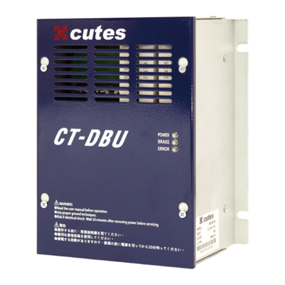
CUTES DBU304-045 Installationshandbuch - Seite 4
Blättern Sie online oder laden Sie pdf Installationshandbuch für Kontrolleinheit CUTES DBU304-045 herunter. CUTES DBU304-045 7 Seiten. Dynamic braking unit

Dynamic Braking Unit Installation Manual
1. Preface
Thank you for choosing CUTES's breaking module.DBU30 braking unit helps dissipate regenerative energy from the three-phase
induction motor when in applications that required sudden deceleration. With DBU30 Braking Unit, the regenerative energy will be
dissipated in dedicated braking resistor. To prevent electrical fire or human injury, follow the instruction manual before wiring. The
DBU30 braking unit is designed for use with the CUTES's VFD models. The Braking Resistor is designed for use with DBU30
braking unit(Refer to this manual for more information).When ordering new copies of the manual, contact a CUTES representative
or download on our documentation website(http://www.cutes.com.tw/) 。
2. Specifications
DBU Braking Unit Selection
Operation Explanation:
For safety consideration,
1.
install an overload relay
between the braking unit and
the braking resistor. In
conjunction with the magnetic
contactor (MC) prior to the
drive, it can perform complete
protection against
abnormality.
2.
The purpose of installing
the thermal overload relay is
to protect the braking resistor
from damage due to frequent braking, or due to braking unit keeping operating resulted from unusual high input voltage. Under
such circumstance, just turn off the power to prevent damaging the braking resistor.
Please refer to the specification of the thermal overload relay.
3.
The alarm output terminals (RA, RC) of the braking unit will be activated when the temperature of the heat sink exceeds
4.
95°C. It means that the temperature of the installation environment may exceed 50°C or the braking %ED may exceed 10%ED.
Braking Resistor Selection
