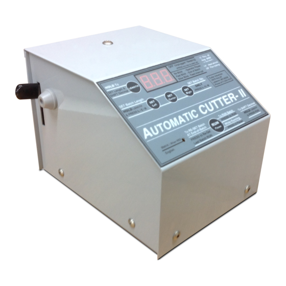
Cutter Industries Automatic Cutter III Setup-Handbuch - Seite 2
Blättern Sie online oder laden Sie pdf Setup-Handbuch für Kutter Cutter Industries Automatic Cutter III herunter. Cutter Industries Automatic Cutter III 2 Seiten.

Set-up Guide for the Automatic Cutter II & III
Use this set-up guide when you have to make adjustments or need to troubleshoot
our automatic cutting machines.
Workbench Attachment
You can secure the Automatic Cutter II or III to a workbench by inserting 1/4-20 studs
in the bottom of the base plate (front-center and back-center). Next, extend the
studs below the rubber legs to set them into the matching workbench holes (semi-
permanent) or through the holes with nuts and washers below.
Cutting Length Calibration
If you need to use your cutter for different materials, you will need to reset the program
length on the cutter. Different materials or sizes may cut longer/shorter than the originally
programmed length due to their different compression through the feed and count
rollers. There will be some variance. Run a test piece at the desired length to determine
the length variance re-run. Lengthen or shorten to compensate for the variance.
Full One-Year Warranty
Our automatic cutters are warranted to be free of defects in material or workmanship for
one full year from the date of purchase (not including the cutting blade or rubber feed
rollers). During this warranty period, the unit will be repaired or replaced at our option.
Please see our website for deatiled information and instructions if your automatic
cutter needs service.
AutomaticWireCutter.com/automatic-cutter-warranty-and-service
Internal Access (after 1-year warranty expires)
Doing Your Own Repairs
For owners who would like to do their own service on units that are out of warranty,
call us for standard replacement parts at (417) 533-1019.
• Disconnect from 120V power source.
• Remove exit-side - Remove base-screws and pull off.
• Remove back - Remove base-screws and slide down.
• Remove front-top (not required for normal service).
• Remove base-screws and top-screw, then roll to the side.
• To properly replace the covers...
- Replace front-top - Wires must clear motor-fan and solenoid
- Replace back - Slide up under the front-top lip
- Replace exit-side - Wires must clear motor-fan and solenoid
Cut-Blade Replacement
• Disconnect from 120V power source.
• Remove exit-side and back - See Internal Access, above.
• Remove key and pin - Holds cut-blade to solenoid.
• Remove upper shoulder-bolt - Upper end of cut-blade.
• Drip thread-locker into the shoulder-bolt hole threads.
• Replace the cut-blade and upper shoulder-bolt.
• Adjust cut-blade tightness - See Cut-Blade Adjustment, below.
• Replace pin and key holding the cut-blade to the solenoid.
• Replace exit-side and back - See Internal Access, above.
Cut-Blade Adjustment
• Disconnect from 120V power source.
• Remove exit-side & front-top. See Internal Access, above. With the knife return
spring in place, use a 7/64" allen-wrench to loosen the set screw on the side of
the knife base (the block the knife cuts across). Using a 1/8" allen-wrench, adjust
the tightness of the cut-blade upper shoulder-bolt as tight as possible, so that
when the cut-blade is manually drawn over the exit-hole and released, it returns
fully and freely to its neutral position. Once adjusted, tighten the set screw which
seats into the shoulder of the shoulder screw and holds the adjustment. Attach
case sides before reconnecting to the power source.
