Alutech CUL11 Anschluss- und Betriebsanleitung - Seite 7
Blättern Sie online oder laden Sie pdf Anschluss- und Betriebsanleitung für Kontrolleinheit Alutech CUL11 herunter. Alutech CUL11 20 Seiten.

TEChNICAL SPECIFICATIONS
3.
TEChNICAL SPECIFICATIONS
Supply voltage
Supply frequency, Hz
Electric motor power, kW
Power demand in standby, W
Valve rated supply voltage
Valve rated power, W
Auxiliary equipment power supply
(optical door position sensor)
Light lamp power supply
Section of wires to be connected to connectors, mm
IP degree of protection
Operating temperature range, º С
Overall dimensions, mm
4.
ELECTRIC MODULE
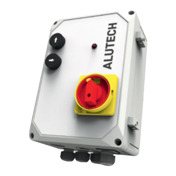
The electric module to which other devices are connected (fig. 2) is located inside the control unit.
List of module elements
Element
Element
FU1
FU2
FU3
FU4
FU5
FU6
FU7
hL1
hL2
hL3
hL4
hL5
INSTALLATION AND OPERATION MANUAL | CUL11 CONTROL UNIT
Parameter name
Parameter name
T10А500V fuses
CAUTION! Use quartz-sand-filled fuses
T2А500V fuse
CAUTION! Use quartz-sand-filled fuse
T3.15А250V fuses
LED indicating the operation of control buttons 2 and 3 (fig. 1). Lights up when
the control button is pressed
LED indicating the electric motor overcurrent in hydraulic unit. Lights up when
the overcurrent protection is triggered
LED indicating the connection of hydraulic unit valves. Lights up when valves are not
connected to VAL1 and VAL2 outputs (or to one of the outputs)
LED indicating the state of door position sensor. Lights up when the sensor is activated
LED indicating the operation of valve connected to VAL1 output. Lights up when the
valve is not connected to VAL1 output or voltage is supplied to the valve
3 ~ 400 V ± 10 %
24 V DC / max. 100 mA
230 V / max. 100 W
2
IP54 (professional installation)
190 × 280 × 145
Description
Description
Value
Value
50
≤ 1.5
≤ 5
24 V DC
18
max. 2.5
– 25 ... + 40
5
5
