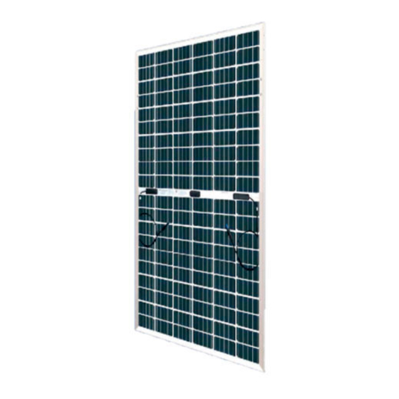
ET Solar ET-M754BH WW Series Installationshandbuch - Seite 6
Blättern Sie online oder laden Sie pdf Installationshandbuch für Sonnenkollektor ET Solar ET-M754BH WW Series herunter. ET Solar ET-M754BH WW Series 19 Seiten. Photovoltaic modules

event of a fire.
Use components or accessories required by local authority. Do not use panels
near equipment or in places where flammable gases may be generated.
ET Solar double modules have been rated type 29/Class A( type 1/Class C for
backsheet module) for fire performance according IEC61730/UL61730.
Confirm mounting slope less than 5 in/ft (127mm/305mm) to maintain a fire class
rating.
4 Mechanical Installation
4.1 Installation requirement
ET Solar bears NO responsibility for any damage caused by the use of unsuitable or
inappropriate mounting / fixing systems. Before starting with the mounting process,
the strength of mounting / fixing structure on the panel field must meet the local
loading condition, e.g. wind, snow, earthquake, and so on.
Selecting the location& Tilt Angle
4.1.1
Select a suitable location for installation of the module.
For optimum performance, the module must be facing true south in northern
latitudes and true north in southern latitudes.
For detailed information on optimal module orientation, refer to standard solar
photovoltaic installation guides or a reputable solar installer or systems
integrator.
Shading on the module will reduce electricity production.
Do not install the module near equipment or in locations
where flammable gases can be generated or collected.
A minimum angle of 10° is recommended in order to make
it easier for dust to be washed off by rain.
Selecting the proper mounting structure and hardware
4.1.2
Observe all instructions and safety precautions applicable to the mounting
system to be used with the module.
Do not drill holes in the glass surface of the module. Doing so will void the
warranty.
Modules must be securely attached to the mounting structure. If heavy wind or
snow loads are anticipated, additional mounting measuresshould also be used.
Load calculations are the responsibility of the system designer or installer.
The mounting structure and hardware must be made of durable, anti-corrosion
and UV-resistant material.
4.2 Mounting methods
Mounting with bolts
4.2.1
4 or 8 pre-drilled mounting holes, located on the aluminum alloy frame, are
provided for ease of installation. They are designed to be used with metric M8
stainless steel screws. We recommend to use a tighten torque of 16~20
www.etsolar.hk
N.m
- 4 -
3
3
