Fleet Management MLT-400i Installationshandbuch - Seite 11
Blättern Sie online oder laden Sie pdf Installationshandbuch für GPS Fleet Management MLT-400i herunter. Fleet Management MLT-400i 14 Seiten.
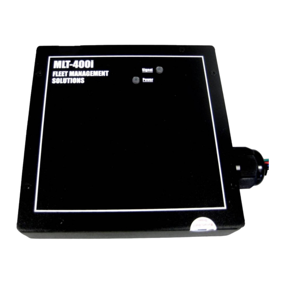
MLT-400i Installation Guide
Appendix A – ANTIR01 Antenna Installation
• Keep antenna at least two feet from all other antennas
• Size: 3.5"L, 2.2"W, 0.8"H
• The ANTIR01 does not require a metal mounting surface
• Recommended holes: 0.5937" (19/32), 2 places, clear-
ance for Iridium and GPS connectors; 0.107 (#36), 4 places,
size for 6-32 self tapping screws
• Hole plug: for 0.5937 holes use Heyco 1675 (black) or 1676
(white); for use when removing antenna
• Use hole template below as a drill guide. Check printed tem-
plate is sized to 1.660" between holes as dimensioned on the
template.
• The connector located closest to the center is for the GPS ca-
ble (Blue), the connector located closest the end is for the
Iridium cable (Black)
• Verify the template size with the actual antenna in case any scaling issues have
occurred during the printing process.
GPS (Blue)
.5937" (19/32)
Diameter
Iridium (Black)
.5937" (19/32)
Diameter
11/18/2009
.107" (#36)
Diameter
4 Places
1.660"
FMS MLT-400i Installation Guide 4.3
Appendix A – ANTIR01 Antenna Installation
.107" (#36)
Diameter
4 Places
GPS (Blue)
.5937" (19/32)
Diameter
Iridium (Black)
.5937" (19/32)
Diameter
1.660"
11