FLENDER ELPEX-B EBWN 630 Handbuch - Seite 11
Blättern Sie online oder laden Sie pdf Handbuch für Industrielle Ausrüstung FLENDER ELPEX-B EBWN 630 herunter. FLENDER ELPEX-B EBWN 630 20 Seiten. Highly flexible couplings
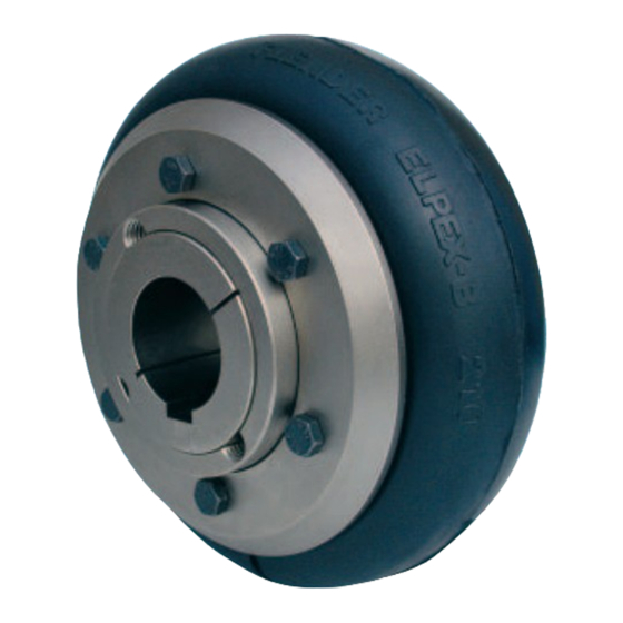
Hochelastische Kupplungen
Bauart EBWZ
Abmessungen
11.I Tabelle / Table / Tableau
Bohrung
Bore
Alésage
Bauart
Teil-Nr.
Größe
Part no.
Type
Nº de partie
Size
Size
Type
y
3
4
Taille
T ill
D
1
mm
EBWZ 105
10...25 10...25
EBWZ 135
11...32 11...32
EBWZ 165
14...42 14...42
EBWZ 190
14...50 14...42
EBWZ 210
16...60 14...50
EBWZ 235
16...60 16...60
EBWZ 255
25...75 16...60
EBWZ 280
25...75 25...75
EBWZ 315
35...90 25...75 46...100 3525
EBWZ 360
35...90 35...90 46...100 3525
1) Massenträgheitsmomente J und Gewichte
gelten für mittlere Bohrungen einschließlich
Taper-Spannbuchse und Reifenanteil.
2) Zur Montage Spezialwerkzeug erforderlich.
K4251 DE/EN/FR
Highly Flexible Couplings
Type EBWZ
Dimensions
Größen / Sizes / Tailles 105 ... 360
Teil 3 / 4
Part 3 / 4
Partie 3 / 4
Buchsen-Nr.
Bush no.
Nº de douille
Teil-Nr.
d
d
Part no.
a
2
Nº de partie
5
3
4
mm mm mm mm
...42
1008
1008 104
70
...55
1210
1210 134
90 125
...55
1610
1610 165
90 125
...75
2012
1610 187 125 180
...75
2517
2012 211 125 180
...75
2517
2517 235 125 180
...90
3020
2517 254 150 225
...90
3020
3020 280 150 225
3020 314 165 250
3525 359 165 250
1) Mass moments of inertia J and weights refer
to couplings with medium-sized bore incl.
Taper bush and tyre part.
2) Special tools required for assembly.
ELPEX-B
Teil 3
Teil 6
Part 3
Part 6
Partie 3
Partie 6
Teil-Nr.
Part no.
Nº de partie
d
d
L
3
4
z
3
4
5
l
1
mm
mm
95
25
22
22
45
96
93
32
25
25
50
133
2)
93
32
25
25
50
133
93.5
48
32
32
80
133.5
173.5
133.5
48
45
32
80
173.5
133.5
48
46
46
80
173.5
133.5
60
51
45 100
173.5
133.5
60
52
52 100
173.5
134.5
80
66
51 110
174.5
134.5
80
65
65 110
174.5
Accouplements à haute élasticité
Type EBWZ
Dimensions
Teil 5
Part 5
Partie 5
Massenträg-
heitsmoment
von
bis
Mass moment
from
up to
of inertia
S
2
de
à
Moment d'inertie
min
3 / 4
3 + 5 + 6
1)
S
J
3
2
mm
kgm
6
100
116
0.0009
2)
100
116
9
0.0019
140
156
100
124
9
0.0049
140
164
100
114
9
140
154
0.0083
180
194
140
156
9
0.016
180
196
140
158
9
0.019
180
198
140
158
9
0.049
180
198
140
156
9
0.075
180
196
140
160
9
0.11
180
200
140
163
9
0.26
180
203
1) Moments d'inertie J et poids valables pour des
alésages moyens avec douille Taper et part
de l'élément élastique.
2) Un outillage spécial est nécessaire pour le
montage.
Gesamt-
gewicht
Total
weight
Total
Total
poids
oids
kg
0.0027
4.2
0.0085
6.5
0.012
8.2
0.046
18
0.053
21
0.056
21
0.15
36
0.17
43
0.28
52
0.43
68
11