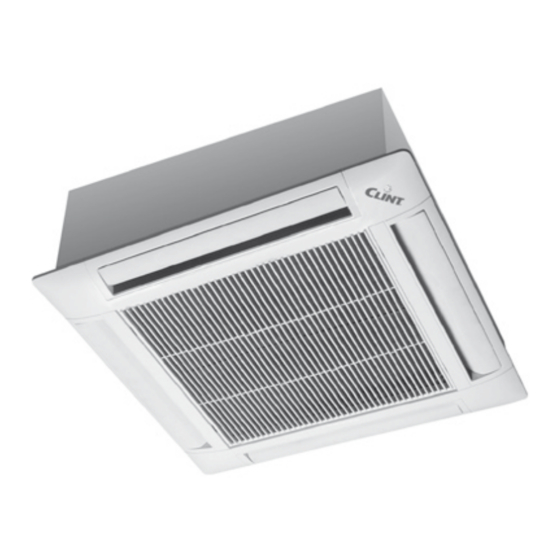
Clint TCW 42 Handbuch für Installation, Gebrauch und Wartung - Seite 6
Blättern Sie online oder laden Sie pdf Handbuch für Installation, Gebrauch und Wartung für Klimagerät Clint TCW 42 herunter. Clint TCW 42 10 Seiten.
Auch für Clint TCW 42: Anleitung für Installation, Gebrauch und Wartung (11 seiten)

2.8 Jednostka dla systemu 2 i 4 rurowego: modele 84÷104
Schemat elektryczny: warianty konstrukcyjne mogą wymagać modyfi-
kacji, zawsze korzystaj ze schematu dołączonego do urządzenia.
Jednostka dla systemu 2-rurowe-
go, z zaworem lub bez, z panelem
sterowania DRM.
LISTWA ZACISKOWA KASETY
PE
L
N
1
3
Q1
2
4
~230 V - 50 Hz
Jednostka dla systemu 2-rurowe-
go, z zaworem lub bez, z panelem
sterowania DRA.
LISTWA ZACISKOWA KASETY
PE
L
N
3
1
Q1
2
4
~230 V - 50 Hz
Jednostka dla systemu 4-rurowego
z dwoma zaworami lub dla systemu
2-rurowego, z zaworem lub bez,
grzałką elektryczną i panelem ste-
rowania DRA.
LISTWA ZACISKOWA KASETY
PE
L
N
3 4 5
1
3
Q1
2
4
16 17 18
~230 V - 50 Hz
CV1/CV2
Skraplacz / Condenser
FV
Warystor / Varistor
KRX
Przekaźniki alarmowe / Alarm relais
L
Faza / Phase
Silnik pompki skroplin /
MP
Drain pump motor
MV1/MV2 Silnik wentylatora / Fan motor
N
Zero / Neutral
Unit for system with 2 pipes, with
or without valve, with DRM control
panel.
N L
230 Vac
Unit for system with 2 pipes, with
or without valve, with DRA control
panel.
N L
230 Vac
SM
Unit for system with 4 pipes, with
two valves, or with 2 pipes, with or
without valve and electric heater,
with DRA control panel.
1
7
6
2
7
6
20
19
15
14
N L
230 Vac
SM
PE
Uziemienie / Ground
Q1
Zabezpieczenie / Protection
QG
Zabezpieczenie / Protection
SB
Czujnik poziomu wody / Water level sensor
SM
Czujnik min. temperatury wody / Sensor min. water temp.
X
Listwa zaciskowa / Power terminal block
YC
Zawór 3-drogowy (4R) / 3-way valve (4 T)
YF
Zawór 3-drogowy / 3-way valve
2.8 Unit for 2 and 4 pipes system: models
Main layout: the variants made in the constructions can involve modifi -
cations. Always refer to the layout supplied with the product.
CV2
MV2
56
55
54
53
56
56
11
KRX
14
PE
L
N
2
3
1
3
QG
2
4
YF
230V-50Hz
CV2
MV2
56
55
54
53
56
56
11
KRX
14
PE
L
N
2
3
1
3
QG
MAX
4
2
YF
230V-50Hz
84 - 104
1
19
14
CV1
MV1
55
54
53
21
KRX
22
24
55
54
53
12
3
4
5
6
7
1
19
14
CV1
MV1
55
54
53
21
KRX
22
24
55
54
53
12
3
4
5
6
7
MIN MED
YC
GRZANIE /
HEAT
13
BK
Czarny / Black
BN
Brązowy / Brown
BU
Niebieski / Blue
GN/YE
Żółto-zielony / Green-Yellow
GY
Szary / Grey
OG
Pomarańczowy / Orange
WH
Biały / White
Minimalna prędkość / minimum speed
min
med
Średnia prędkość / medium speed
max
Maksymalna prędkość / maximum speed
MP
SB
15
FV
A1
KRX
U
A2
31
KRX
32
34
X
8
9
10
CHŁODZENIE /
COOL
MP
SB
15
FV
A1
KRX
U
A2
31
KRX
32
34
X
8
9
10
CHŁODZENIE /
COOL
