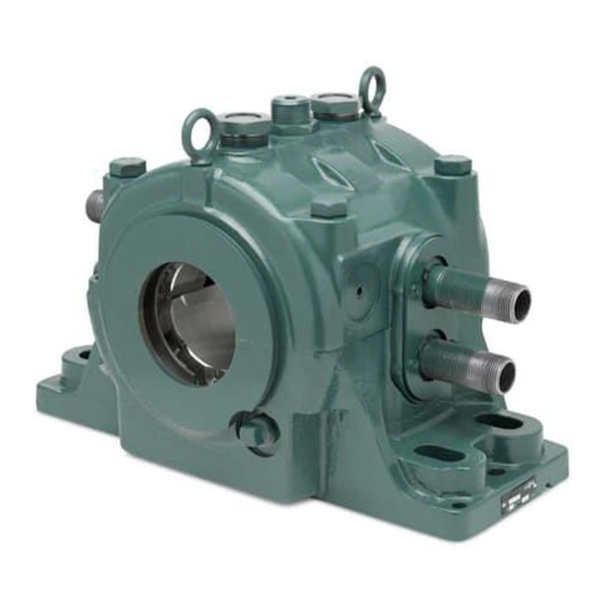
Dodge Sleevoil STL 12 PLAIN Gebrauchsanweisung - Seite 4
Blättern Sie online oder laden Sie pdf Gebrauchsanweisung für Industrielle Ausrüstung Dodge Sleevoil STL 12 PLAIN herunter. Dodge Sleevoil STL 12 PLAIN 8 Seiten. Pillow blocks

Check construction drawing for proper coolant flow rate. If not
given, use flow rate shown in the following table as a general
starting point for proper cooling. Lower coolant inlet temperature
and (or) lower ambient temperature require less flow. If the
coolant inlet temperature exceeds 90ºF additional coolant will be
required. The interior pressure of the liner should never exceed
120 psi. Unless specially ordered. Anti-freeze type additives may
be used with the water in cold operating environments, otherwise
purge all coolant from the liner by blowing out with compressed
air or steam anytime bearing coolant is subject to freezing.
Any questions on installation, maintenance, or arrangement of
coolant connection inlets and outlets should be referred to the
equipment manufacturer
CAUTION: The fluid or air pressure should never exceed 120
p.s.i.
OPTIONS
Thermocouple or RTD. A thermocouple is used to sense the
operating temperature in the shaft area. If a pre-set thermal limit
is exceeded it can trigger a warning or shut-down. There is no
substitute for proper condition monitoring. All Sleevoil bearings
should contain either an RTD or Thermocouple.
temperatures are not an accurate display of internal bearing
temperature.
Two 1/2-14 N.P.S.F. threaded holes on the side opposite the
"X" marking have been provided as a standard means of
thermocouple mounting. Also furnished with the pillow block is
a 1/2"x1/8" adapter bushing to allow adaption of thermocouples
from several manufacturers. Spring loaded thermocouples
are recommended for positive contact.
Install the thermocouple in the location shown on the
construction drawing. Make certain the probe extends into
the liner thermocouple hole. For non-expansion bearing, the
thermocouple should be located in the hole nearest to the
end carrying the thrust load. When the direction of the thrust
load is not known, two thermocouples are recommended. For
expansion bearings, the thermocouple can be located at either
end. Depending on thermocouple and bearing size it may be
necessary to employ a system of pipe nipples and couplings to
achieve proper probe penetration and housing clearance. Use
sealant on all threaded connections including thermocouple
mounting thread. Apply sealant to the pipe plug furnished and
install it in the other hole.
Thermostat and Immersion Heater. An immersion heater is
used to maintain a minimum oil temperature in the pillow block.
The thermostat, used in conjunction with the heater, monitors
oil temperature in the pillow block and regulates the immersion
heater.
If the pillow block has been machined for a heater and thermostat
the threaded mounting holes are usually located in the end face
of the housing base. Install heater and thermostat using sealant
on all threaded connections to prevent oil leakage.
CAUTION: Before filling and draining oil from pillow block
be sure heater is off or it will overheat when not submerged
in oil.
WARNING: When installing heater and thermoswitch,
follow directions and safety procedures recommended by
manufacturer. Install wiring in accordance with National
Electric Code and local codes.
Circulating Oil. If using circulating oil, a circulating oil inlet kit
must be used. Circulating oil inlet kits make use of the existing
inspection cover ports on top of the bearing.
inspection ports and use the supplied screws to attach the clear
Housing
plate to the bearing. Insert the 1/4" NPT threaded pipe nipples
into the clear plates. Pipes extend through the clear plates and
are directed toward the inspection holes in the liner. The standard
drain arrangements are shown. Consult manufacturers drawing
for exact dimensions and location of drain(s).
Install oil supply lines to the 1/4" N.P.T. external (male) threaded
inlets so that each inlet will receive an equal amount of oil. Make
sure that the oil flows from the pipes directly into the inspection
holes. Drain piping should be vented and of adequate size to
drain oil from the bearing at the specified flow rate. The housing
drain must be directed straight down into a return drain sloping
away at a 15 degree or greater angle from the horizontal. The
oiling system must have a means of filtering the oil to remove
any contaminating particles. A 25 micron filter or better is
recommended.
When baffles are installed in oil ring grooves of upper liner, oil
rings cannot be used and should be discarded. Bend baffle so
that free end rests on lower liner joint. Since the housing drain is
arranged to maintain the proper oil level, then oil rings may be
used as a safety measure of back-up oiling system without oil
baffles.
4
Remove the
