DOEPFER Quad AD/LFO A-143-1 Handbuch - Seite 3
Blättern Sie online oder laden Sie pdf Handbuch für Kontrolleinheit DOEPFER Quad AD/LFO A-143-1 herunter. DOEPFER Quad AD/LFO A-143-1 8 Seiten.

System A-100
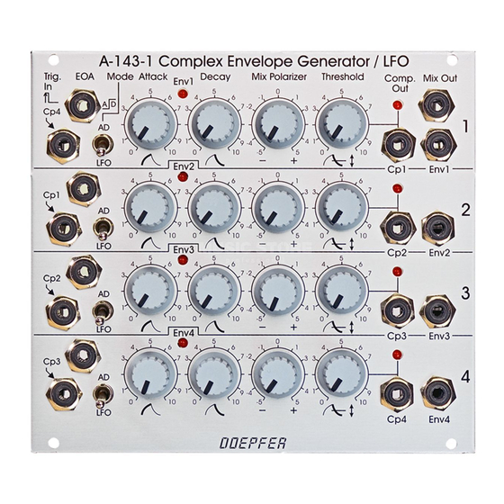
Quad AD/LFO A-143-1
DOEPFER
Provided that the trigger inputs are not patched the four
units are daisy chained via the comparator outputs (Cp Out)
as they are normalled via the switching contacts of the
trigger input sockets, i.e. each unit is triggered by the Cp
output of the preceding unit. Fig. 4 shows both the
behaviour of the module in the default state (complex/multi-
state LFO) and with a trigger signal applied to trigger input 1
(complex envelope generator).
The rising edge of Cp1 triggers the unit 2, the rising edge of
Cp2 triggers the unit 3 and so on. The example uses
different Attack, Decay and Threshold settings for each unit.
At the bottom of the picture two possible mixes are shown:
For the first mix all envelope signals are added up with the
same level and polarity (+1), i.e. all polarizer controls are in
the fully clockwise position. For the second mix the
level/polarity is +1 for the units 1 and 4, and –1 for the units
2 and 3, i.e. the polarizer controls of unit 1 and 4 are fully
clockwise and the polarizer controls of unit 2 and 3 are fully
counter-clockwise.
The dashed lines at the right end of the mix graphs are valid
if the module is in the cyclic mode, i.e. if the comparator
output 4 is normalled to the trigger input 1 (i.e. default
without external trigger signal). The permanent lines are
valid if an external trigger signal is used to trigger unit 1 (i.e.
the daisy chain is interrupted at trigger input 1).
Fig. 4: Complex envelope generator / LFO
3
