Doepke Dupline DSS 4R-EIB Betriebsanleitung - Seite 7
Blättern Sie online oder laden Sie pdf Betriebsanleitung für Zubehör Doepke Dupline DSS 4R-EIB herunter. Doepke Dupline DSS 4R-EIB 12 Seiten. Operating signal sensors with acknowledgement feature

Doepke
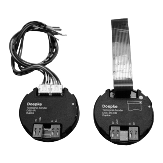
DSS 4R/DSS 4R-EIB Operating Signal Sensors
6. General Information
The DSS 4R and DSS 4R-EIB operating signal sensors are components of the Dupline
installation system and enable conventional and EIB push-buttons to be linked to the
system. They are provided with 4 input and 2 acknowledge channels and, in addition,
offer the possibility of indicating the bus status (BUS-OK LED). Because of their com-
pact design the operating signal sensors can be fitted behind a push-button in a stand-
ard flush-mounted installation box.
Conventional push-buttons and potential-free switching contacts can be operated with
the DSS 4R via two 4-wire system cables supplied complete with end ferrules. An inter-
nal extended operating signal prevents any multiple switching occasioned by possible
contact bounce.
The 24 V acknowledgement outputs of the DSS 4R are each designed for loads of max.
80 mA (2 W). Basically, any desired indicator lights may be employed; however, the
maximum loading capacity may not be exceeded when using incandescent lamps. For
this reason - and because of the longer lifespan - we recommend the use of LEDs.
EIB-enabled 2-way-switches of manufacturers Berker, Gira, Jung and Siemens can be
linked to the Dupline bus with the aid of the DSS 4R-EIB. Connection is made easy with
the supplied flexible circuit board complete with system plug connecters.
7. Coding
With the DHK 1 hand encoder each channel can be assigned any address between A1
and P8 via the pin strip at the side of the signal sensors. The allocation of the channels
is as follows:
Channel
1
Input operating signal 1 (T1)
2
Input operating signal 2 (T2)
3
Input operating signal 3 (T3)
4
Input operating signal 4 (T4)
Channels which are not required should remain uncoded.
Encoding the sensors requires neither a supply voltage nor the Dupline signal and is
carried out with the aid of the DKP 2 flat-plug coding cable. Attention should be paid to
the correct polarity of the coding cable; incorrect polarity will not, however, cause per-
manent damage.
Although the coding is permanently retained, it may always be overwritten.
3931176/08/12/D - The right to make technical changes reserved!
Operating Instructions
Description
1Table of Contents
Channel
5
Acknowledge signal 1 (LED1)
6
Acknowledge signal 2 (LED2)
7
Not assigned
8
Not assigned
Description
7
