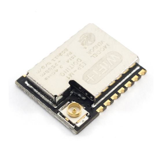
Doiting ESP-M1 Benutzerhandbuch - Seite 13
Blättern Sie online oder laden Sie pdf Benutzerhandbuch für Drahtloser Router Doiting ESP-M1 herunter. Doiting ESP-M1 19 Seiten.

®
DOITING
8. Minimum User System
This module can work just at 3.3V working voltage:
Note
(1) the working voltage for module is DC 3.3V;
(2) the max current from IO of this module is 12mA;
(3) RST Pin is enabled when it is low level; and EN pin is enabled when it is high level;
(4) WiFi module is at update mode: GPIO0 is low level, then module reset to power; Wi-Fi module
is at working mode: GPIO0 is at high level, and then reset to power;
(5) Wi-Fi module is connected to RXD of the other MCU, and TXD is connected to RXD of the
other MCU.
9. The Recommended PCB Design ( Take ESP-M2 as an Example)
ESP-Mx Wi-Fi module can be sold on PCB board directly. For the high RF performance for the device,
please notice the placement of the module. There are three ways to use the module.
Solution 1:optical solution. The WiFi module is placed on the side of the board, and the antennas are
all exposed, and there is no metal material around the antenna, including wires, metal casings, weight
plates, and the like.
Solution 2:suboptical solution. The WiFi module is placed on the side of the board, and the antenna
below is hollowed out. There is a gap of not less than 5 mm reserved with the PCB, and there is no metal
material around the antenna, including wires, metal casings, weight plates, and the like.
Solution 3: The WiFi module is placed on the side of the board, and the PCB area under the antenna is
empty, and copper cannot be laid.
Doctors of Intelligence & Technology (www.doiting.com) Copyright@2014-2019
ESP-M1/M2 User Mannual
Fig.8.1 minimum system
Page 10
