CYP PUV-2100TX-AVLC Betriebshandbuch - Seite 9
Blättern Sie online oder laden Sie pdf Betriebshandbuch für Transmitter CYP PUV-2100TX-AVLC herunter. CYP PUV-2100TX-AVLC 20 Seiten. Hdbaset 4k/hdr transmitter (100m)

6. OPERATION CONTROLS AND FUNCTIONS
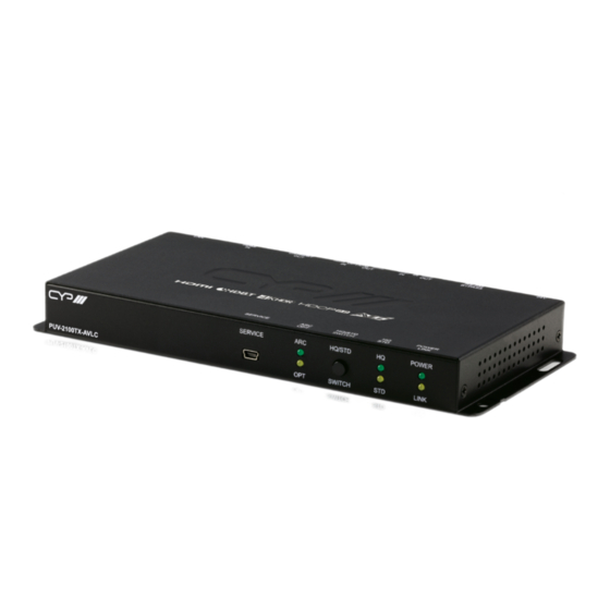
6.1 Front Panel
PUV-2100TX-AVLC
1
SERVICE Port: This port is reserved for firmware update and serial
control use only.
2
ARC & OPT LEDs: These LEDs illuminate to indicate if the optical
output source is coming from the optical input or ARC on the
connected Receiver.
Note: Selecting ARC as a source requires a compatible Receiver.
3
HQ/STD SWITCH Button: This switch allows the user to select which
compression mode to use when AVLC is required. A single press
toggles between modes.
HQ (High Quality) mode uses the least amount of compression and
provides the highest possible visual quality (perceptually identical to
the original). In this mode, AVLC compression activates for any signal
requiring more than 9Gbps.
STD (Standard Quality) mode applies additional signal reduction
methods to lower the bandwidth requirements even further,
improving transmission reliability at the cost of some visual fidelity. In
this mode, AVLC compression activates for any signal requiring more
than 7.5Gbps.
4
HQ/STD LEDs: These LEDs illuminate to indicate which AVLC mode is
selected: HQ (High Quality) or STD (Standard Quality).
5
POWER LED: This LED will illuminate to indicate the unit is on and
receiving power.
LINK LED: This LED will illuminate solidly when a live connection with
a compatible Receiver is active.
SERVICE
ARC
HQ/STD
OPT
SWITCH
1
2
3
HQ
POWER
STD
LINK
4
5
9
