DOLD BH 5911 Betriebsanleitung - Seite 5
Blättern Sie online oder laden Sie pdf Betriebsanleitung für Kontrolleinheit DOLD BH 5911 herunter. DOLD BH 5911 20 Seiten. Multi-function safety system safemaster m control unit

Operating instructions
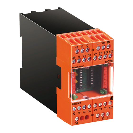
Multi-Function Safety System SAFEMASTER M
Control Unit
BH 5911
Before installing, operating or maintaining this device, these instructions
must be carefully read and understood.
DANGER
Dangerous voltage.
Electric shock will result in death or serious injury.
Disconnect all power supplies before servicing equipment.
CAUTION
Safe operation of the device is only guaranteed when using certified
components!
Important Notes
The product hereby described was developed to perform safety functions
as a part of a whole installation or machine. A complete safety system
normally includes sensors, evaluation units, signals and logical modules
for safe disconnections. The manufacturer of the installation or machine
is responsible for ensuring proper functioning of the whole system. DOLD
cannot guarantee all the specifications of an installation or machine that
was not designed by DOLD. The total concept of the control system into
which the device is integrated must be validated by the user. DOLD also
takes over no liability for recommendations which are given or implied in
the following description. The following description implies no modification
of the general DOLD terms of delivery, warranty or liability claims.
Safety Regulations
-
This device must be installed and operated by trained staff who are
familiar with these instructions and with the current regulations for safety
at work and accident prevention.
-
Pay attention to applicable local regulations, especially regarding safety
measures.
-
Opening the device or implementing unauthorized changes voids any
warranty
-
The unit should be panel mounted in an enclosure rated at IP 54 or
superior. Dust and dampness may lead to malfunction.
-
Adequate fuse protection must be provided on all output contacts with
capacitive and inductive loads.
-
The safety function must be triggered during commissioning
Designated Use
The Multi-Function Safety System is used to enable and interrupt a safety
circuit in a safe way. It can be used to protect people and machines in ap-
plications with e-stop buttons, safety gates, light curtains with selftesting
(Type 4) acc. to IEC/EN 61 496-1, 2-hand controls for presses as well
as other production machinery with dangerous closing action (Type III A
or III C to EN 574). When used in accordance with its intended purpose
and following these operating instructions, this device presents no known
residual risks. Nonobservance may lead to personal injuries and damages
to property.
Safety Notes
ATTENTION - AUTOMATIC START!
According to IEC/EN 60 204-1 part 9.2.5.4.2 and 10.8.3 it is not allowed
to restart automatically after emergency stop. Therefore the machine
control has to disable the automatic start after emergency stop.
All technical data in this list relate to the state at the moment of edition. We reserve the right for
technical improvements and changes at any time.
ENGLISH
of the original instructions
Main Features
• According to
- Performance Level (PL) e and category 4 to EN ISO 13849-1: 2008
- SIL Claimed Level (SIL CL) 3 to IEC/EN 62061
- Safety Integrity Level (SIL 3) to IEC/EN 61508
- Category 4 to EN 954-1
• For emergency stop function, the following inputs
and outputs are available:
Inputs:
Outputs:
• Parallel connection of several SAFEMASTER M-systems possible
• The functions are selected via rotary switch
- 1 Emergency stop circuit, 2-channel
- 2 Emergency stop circuits, single-channel
- 1 Emergency stop circuit, 2-channel + 1 stop single channel
• Auto or manual start
• 2 semiconductor outputs for status indication
• LEDs for status indication
• Overvoltage and undervoltage monitoring function with error indication
• Permanently monitored feedback loop to connect external contactors
• Broken wire and short circuit monitoring function with error indication
• Width: 45 mm
Applications
Realization of fail-safe control circuits for protection of people and machinery
Connection Terminals
Terminal designation
General Information SAFEMASTER M
The maximum configuration of the SAFEMASTER M multi-function safety
system is as follows:
• the control unit BH 5911
• up to 3 input modules BG/BH 5913, or BG/BH 5914, BG/BH 5915
• up to 3 output modules BG 5912
• 1 diagnostic module BG 5551 for CANopen, or
• 1 diagnostic module BG 5552 for Profibus-DP
The BH 5911 controls the whole system.
The input/output modules can be used to expand the control unit in a
modular way into a multi-functional safety system.
To transmit status messages of the individual modules to a moni to ring or
control unit, one of the following diagnostic modules may be connected:
• BG 5551 for CANopen
• BH 5552 for Profibus-DP
5
Translation
4 monitored start inputs, or
3 start inputs and 1 stop input and
2 Emergency stop inputs
3 NO contacts, or
2 NO contacts/1 NC monitoring contact
S11
Emergency stop button 1
S12
S13
Emergency stop button 2
S14
X11-T1
X11-T2
X12-T3
X12-T4
Feedback loop for external
Y1-Y2
Signal designation
Start button 1
Start button 2
Start button 3
Start button 4 or stop
contact extensions
BH 5911 / 151007 / 478
