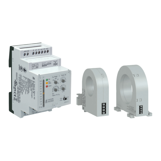
DOLD IL 5882.38 Installation / Überwachungstechnik - Seite 4
Blättern Sie online oder laden Sie pdf Installation / Überwachungstechnik für Messgeräte DOLD IL 5882.38 herunter. DOLD IL 5882.38 8 Seiten. Residual current monitor

Accessories
Residual Current Transformer ND 5016/024, ND 5016/035
D
C
k
for DIN rail mounting or screw mounting
ND 5016/024
øD
L
Dimension/mm
24
82
Weight / g
Article number
ND 5016/035
øD
L
Dimension/mm
35
88
Weight / g
Article number
Drill tolerance for screw mounting: ± 0.5 mm
*
)
Technical Data Residual Current Transformer ND 5016, ND 5019
Ambient temperature
ND 5016:
ND 5019:
Inflammability class:
Nominal insulation voltage
acc. to IEC 60 664-1:
Rated impulse voltage /
pollution degree:
Voltage test acc. to
IEC/EN 60 255:
Transformation ratio:
Length of connection wires
Type of wire:
Single wire:
Single wire Twisted pair:
Screened wire;
screen on terminal k:
Wire cross section
ND 5016:
ND 5019:
Stripping length:
Wire fixing
ND 5016:
ND 5019:
Screw connection:
ND 5016:
ND 5019:
Fixing torque:
DIN rail mounting:
ND 5016/024, /035:
ND 5016/070:
ND 5019:
B
M10979_b
L1
B
H
C
E
F
75
24
54
25
42*
46
approx. 80
0066009
L1
B
H
C
E
F
81
24
67
25
42*
46
approx. 90
0067064
- 20 ... + 60°C / 253 K ... 333 K
- 10 ... + 50°C / 263 K ... 323 K
V0 according to UL94
AC 630 V
6 kV/3
AC 3 kV
500 /1
up to 1 m
up to 10 m
up to 25 m
0.2 ... 1.5 mm
2
0.75 mm
2
8 mm
Terminals with spring connection and
direct (Push in) technology
Box terminals
M3 or M4
M5
0.8 Nm
integrated clips for vertical and
horizontal mounting
integrated clips for horizontal mounting
using mounting adapter ET 5018
Residual Current Transformer ND 5016/070
for DIN rail mounting or screw mounting
ND 5016/070
k
4,2
Dimension/mm
Weight / g
Article number
Drill tolerance for screw mounting: ± 0.5 mm
*
)
k
4,2
Mounting instructions for screw mounting
High forces when mounting may damage the current transformer fixtures.
The fixing clips are designed to support the current transformer. Forces
that are applied by the cable running through the current transformer can
only be tolerated within limitations.
During installation and afterwards please make sure that the wires are
led through the current transformer without applying pressure and remain
stable in that position.
4
D
G
C
C
k
øD
L
H
H1
B
C
70 111 110 115 32
37
approx. 220
0067065
B
M11582_a
F
k
E
G
55
4,2 50* 74*
15.01.20 en / 177A
