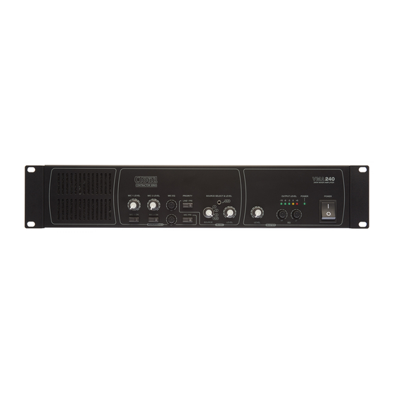
Cloud VMA240 Sicherheitshinweise - Seite 8
Blättern Sie online oder laden Sie pdf Sicherheitshinweise für Verstärken Cloud VMA240 herunter. Cloud VMA240 16 Seiten. Mixer-amplifiers

Internal Settings
WARNING – DANGER
Changing the internal settings requires to open the unit. Prior to opening the unit, the unit shall be disconnected
from any AC supply. Any work on an open unit shall be expedited only by qualified, certified personnel.
Output configuration (hi-voltage/low-impedance)
The output stage of a VMA Series mixer-amplifier may be configured EITHER for driving low impedance loudspeakers (4 ohms
minimum), or for driving 25/70/100 V-line loudspeaker systems.
Units are shipped with the output configured for driving 25/70/100 V-line systems. To convert it for low-impedance operation:
• Disconnect the mixer-amplifier from the AC mains supply.
• Remove the top lid.
• The toroidal output transformer is the larger of the two:
• The transformer's windings terminate in a pair of in-line, multipin connectors. The primary winding (red and black wires)
terminates in a 2-pin female connector, and the secondary winding (blue, white, yellow and purple wires) terminates in a
4-pin female connector. Unplug the 2-pin connector from its header on the vertical PCB mounted on the heatsink at the
left-hand side of the amplifier (viewed from the front). See diagram below:
Connection for
100/70/25 V-line
operation
Power amplifier
output - 2-pin
header on heat
sink PCB
M
Connection for
Lo-Z operation
• Identify the red and black pair of wires from the low-Z output terminals: these also terminate in a 2-pin female connector,
currently unplugged. Plug this into the 2-pin header connector vacated in the previous step.
• Locate jumper J100 on the PCB mounted on the rear panel. This has two positions, ON and OFF. At shipment, it will be
set to ON, placing the 70 Hz high-pass filter in circuit, which is the correct setting when the mixer-amplifier is used with
25/70/100 V-line systems. Using a pair of long-nosed pliers, move J100 to its OFF position.
• Replace the top lid.
If at any time it is necessary to convert the low-impedance output back to 25/70/100 V-line operation, reverse the above
procedure, reconnecting the amplifier output to the transformer primary.
8
VMA Series Installation Guide V1.0
Output
transformer
VMA120/240
Red
F
Black
Pri.
Red
F
Black
Power
transformer
White
Purple
Yellow
Blue
Sec.
100 V
70 V
25 V
COM
F
M
